Overview
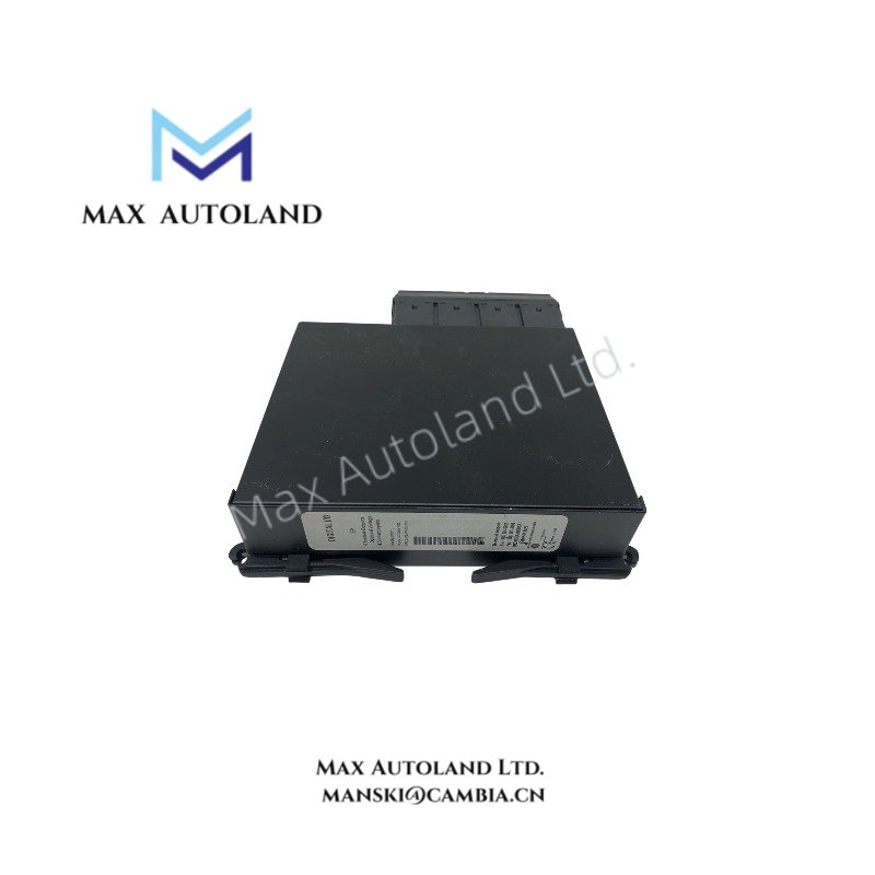
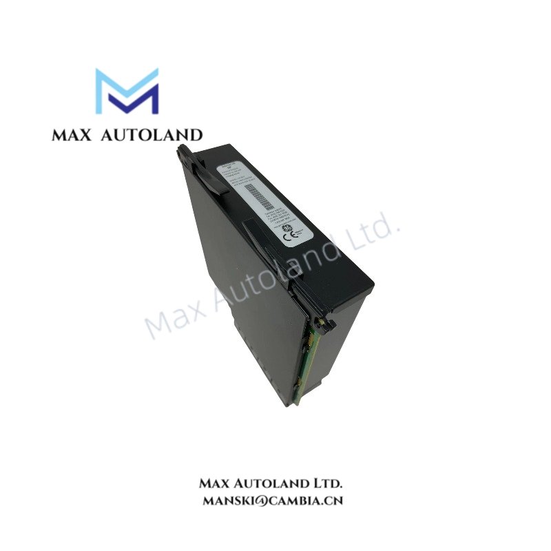
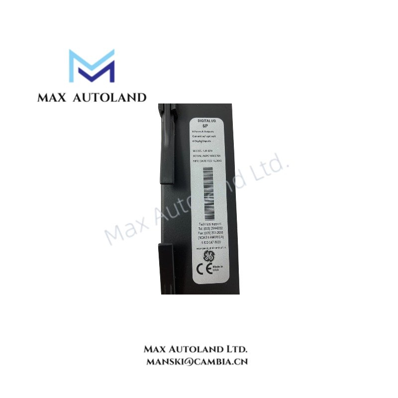
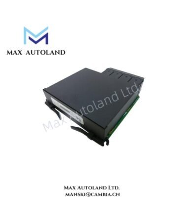
The GE UR6PH, also cataloged as the UR-6PH Heavy-Duty Chassis/Terminal Assembly (Protection & Control Hardware), operates as a dedicated mechanical and electrical interface component providing physical termination, power bus distribution, and EMI-shielded mounting for GE Multilin Universal Relay modules within the UR series substation protection system.
Hardware Specifications
| Parameter | Specification |
|---|---|
| Brand / Model | GE (GE Vernova) UR6PH / UR-6PH |
| Origin | USA / Mexico |
| Weight | approx. 5.5 – 8.5 kg (depending on module loading) |
| Dimensions | 19-inch rack mount (4U typical) or panel mount enclosure |
| Operating Temperature | -40 degC to +60 degC |
| Storage Temperature | -40 degC to +85 degC |
| Humidity | up to 95 % non-condensing @ 55 degC |
| Power Input | 88–300 VDC / 85–264 VAC or 24–48 VDC (depending on fitted PSU module) |
| Power Consumption | typ. < 25 W, max. 45 W fully loaded |
| Dielectric Strength | 2.0 kV AC for 1 min per IEC 60255-5 |
| Insulation Resistance | > 100 MOhm @ 500 VDC |
| Surge Immunity | 4 kV per IEC 61000-4-5 |
| Ingress Protection | Front panel IP54, rear terminals IP20 |
| Communication Buses | Backplane supports IEC 61850, Modbus RTU/TCP, DNP 3.0 via installed CPU module |
Backplane Bus Coupling and Module Firmware Compatibility
The UR6PH chassis provides a parallel multilayer backplane which couples the CPU, I/O, and option cards through a synchronous memory-mapped bus. Module addressing is hardwired by slot position. Installed option cards must match the firmware protocol version encoded in the base relay’s UR-series software image; mixing E-series and legacy U-series firmware builds on the same backplane is not supported. Deterministic scan time is governed by the CPU card and is unaffected by passive chassis components.
Frequently Asked Questions
Q: Can the UR6PH chassis be hot-swapped with the relay powered?
A: No. The UR6PH and its mounted modules are not hot-swappable. Depower the entire assembly before inserting or removing I/O or communication cards to avoid backplane arcing and latch-up.
Q: Does the UR6PH require a specific power supply module to support 24 VDC input?
A: Yes. The chassis itself is passive; a UR-series PSU module configured for 24–48 VDC must be installed in the designated slot. Verify the P/N suffix on the PSU module matches the site DC supply range.
Q: Is the UR6PH compatible with all UR-series relay CPUs (G60, L90, F60, etc.)?
A: The chassis accepts any standard UR CPU module, but the wiring terminal block arrangement (low-profile vs. high-density Phoenix-style) may differ by ordered configuration. Confirm the terminal block P/N against the specific relay model’s hardware manual.
Field Installation Guidelines
- Mount the UR6PH in a 19-inch rack or on a rigid panel using the supplied anti-vibration grommeted screws; torque to manufacturer-recommended values to prevent stress on rear terminal blocks.
- Segregate low-voltage signal wiring (RS485, contact inputs) from high-current AC/DC power and CT/VT secondary conductors by a minimum of 75 mm or use separate cable ducts.
- Terminate shielded communication and analog signal cables with the shield drained to the chassis ground (PE) terminal only—do not connect shield at both ends.
- Verify CT secondaries are shorted before disconnecting from the UR6PH terminal blocks to prevent dangerous open-circuit voltages.
- Ensure rear compartment ventilation clearance of at least 50 mm is maintained for convection cooling of internal PSU and CPU modules.