Overview
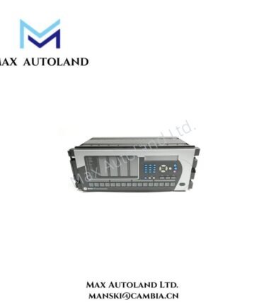
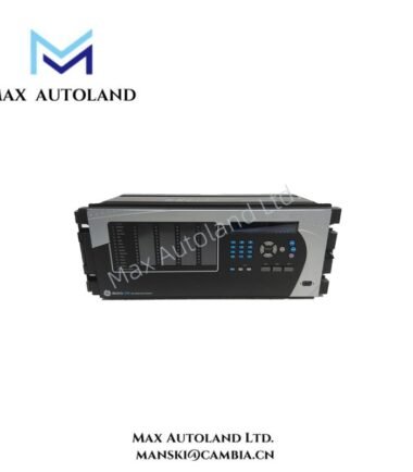
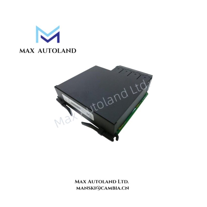
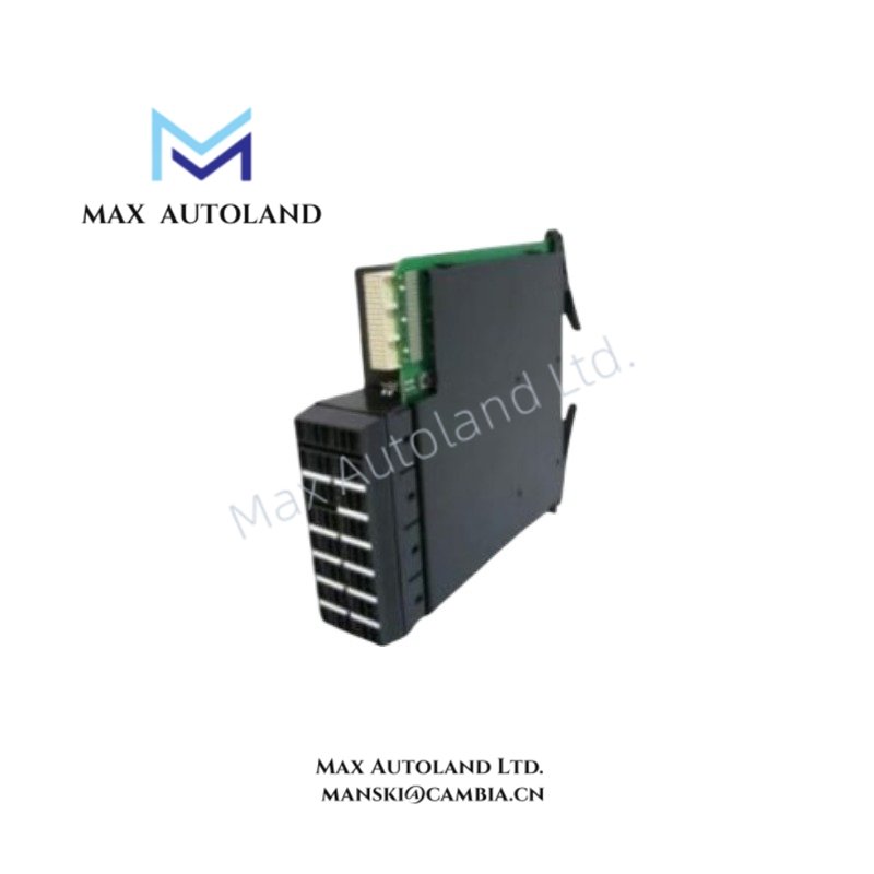
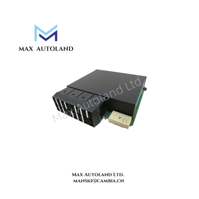
The GE UR8MH, also cataloged as the UR8MH, operates as a dedicated hardware component for secure backplane and field wiring termination within GE Multilin Universal Relay systems.
Configured for physical termination of CT, VT, and I/O field circuits in GE Multilin UR-series relay chassis, the GE UR8MH (UR8MH terminal module) provides direct electrical interface routing between relay internal backplane architecture and external control wiring.
Suffix Breakdown & Model Matrix
No documented suffix segmentation or functional variant matrix is defined for UR8MH. The part is treated as a single hardware identifier used within UR-series chassis assemblies.
Hardware Specifications
| Parameter | Specification |
|---|---|
| ModelBrand | GE UR8MH |
| Origin | USA |
| Weight | 0.35kg |
| OperatingTemp | -40 degC to +60 degC |
| PowerConsumption | Not specified |
| Module Type | Terminal module / rear chassis connector assembly |
| System Compatibility | GE Multilin UR-series relay platforms |
| Mounting | Chassis rear slot / backplane interface |
| Electrical Interface | CT/VT and digital I/O termination routing |
Backplane Communication and Firmware Interface Behavior
UR-Series Backplane Signal Integrity and I/O Density Scaling
The UR8MH interfaces with the UR-series backplane bus architecture used in GE Multilin protection relays. Signal routing is implemented through fixed-pin chassis connectors supporting deterministic internal data exchange between CPU, I/O, and protection modules. I/O density scaling is defined by chassis configuration rather than the terminal module itself.
Firmware update and module recognition are handled at the relay system level. The UR8MH does not execute firmware logic but must maintain connector-level integrity to ensure backplane enumeration consistency during configuration reload or module replacement events.
Frequently Asked Questions
Q: Does the UR8MH support hot-swap operation?
A: The module is mechanically replaceable only under de-energized conditions. Backplane insertion under live system voltage is not specified for operational use.
Q: Does the UR8MH influence backplane current consumption?
A: The module itself does not define processing load. Backplane current draw is determined by installed UR-series functional modules, not the terminal assembly.
Q: Is firmware compatibility affected by UR8MH revision differences?
A: Firmware execution resides in relay CPU modules. The UR8MH does not contain firmware; compatibility is dependent on chassis backplane electrical continuity.
Field Installation Guidelines
Ensure system power is fully isolated before removal or insertion of the UR8MH assembly. Verify that all CT and VT secondary circuits are shorted or isolated according to relay commissioning procedures prior to disconnecting field wiring.
Align the module precisely with the UR chassis guide rails to prevent backplane pin misalignment. Apply uniform insertion force until full seating engagement is confirmed by mechanical stop.
Maintain proper shielding continuity for all field wiring terminated at the module. Cable shields should be grounded at the designated panel earth point in accordance with substation grounding practices to minimize induced noise coupling.