

Overview
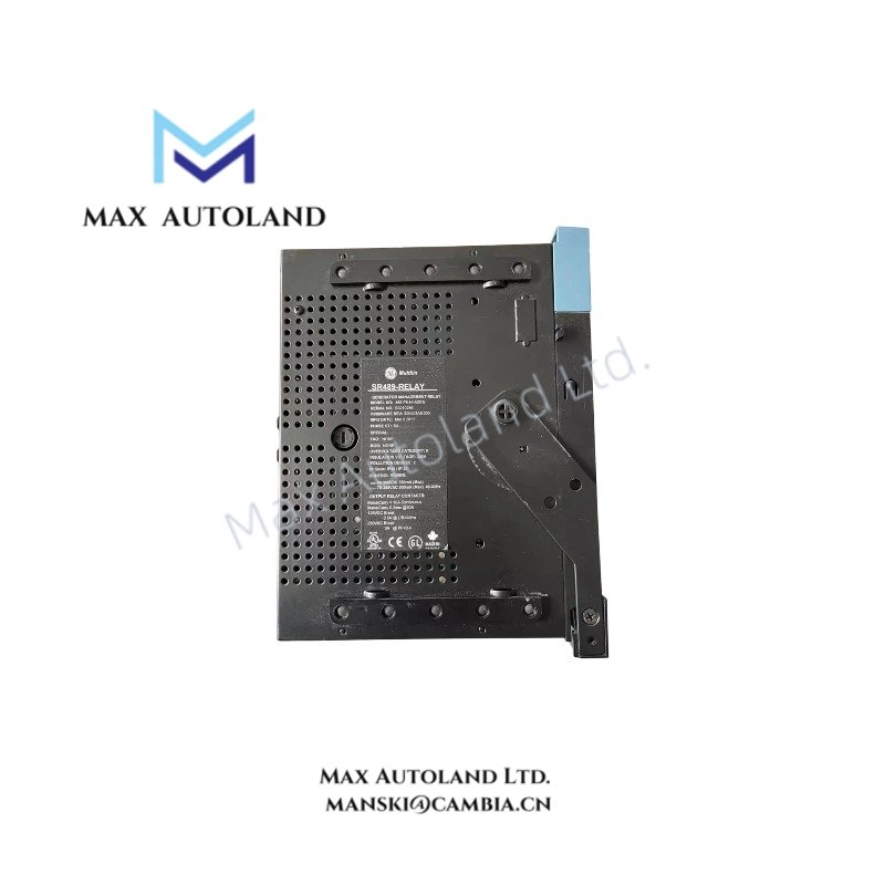
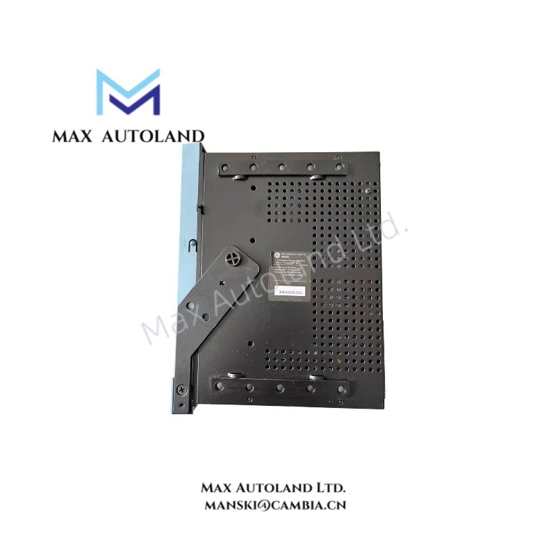
Configured for generator protection and control in utility and industrial power systems, the GE Multilin 489, also cataloged as the SR 489-P5-HI-A20 Generator Management Relay, provides direct physical execution of phase current measurement and control power switching functions.
Hardware Specifications
| Parameter | Specification |
|---|---|
| Model Brand | GE Multilin 489 |
| Origin | Canada |
| Weight | 19 lb 0.0 oz (8.6 kg) |
| Dimensions | 9.0 in x 10.0 in x 10.0 in (22.9 cm x 25.4 cm x 25.4 cm) |
| Operating Temp | -20 degC to +60 degC (typical industrial range) |
| Power Consumption | 90 to 300 V DC; 70 to 265 V AC at 48 to 62 Hz |
| Phase CT Inputs | 5 A secondary |
| Analog Outputs | Four 4 to 20 mA |
| Display Type | Basic Display |
Backplane Bus Communication Velocity Licensing
The GE Multilin 489 interfaces with compatible control system backplanes using deterministic communication protocols. Firmware flash compatibility is enforced through licensed feature sets tied to specific hardware revisions. Communication velocity between relay modules and host controllers is fixed by backplane clock rate and protocol stack configuration, preventing unapproved third-party firmware loads from altering timing performance.
Frequently Asked Questions
Q: Does the SR 489-P5-HI-A20 support hot-swap insertion into an energized case?
A: No. The drawout unit must be inserted or removed only when control power is de-energized to prevent arcing on the backplane connectors.
Q: What is the maximum burden on the phase CT inputs?
A: The CT input burden is limited to 0.2 VA per phase at rated 5 A secondary current.
Q: Are analog output ranges configurable beyond 4-20 mA?
A: No. Output scaling is fixed at 4-20 mA and cannot be reconfigured to other current ranges without replacing the hardware variant.
Field Installation Guidelines
Mount the drawout unit into a compatible SR489 case secured to a rigid panel surface. Torque terminal screws to manufacturer-recommended values. Maintain separation between AC power wiring and CT/analog signal wiring to reduce electromagnetic coupling. Connect shield drains to ground at a single point on the relay side. Verify control power polarity before energizing. Ensure adequate clearance for ventilation openings on both sides of the enclosure.