




Overview
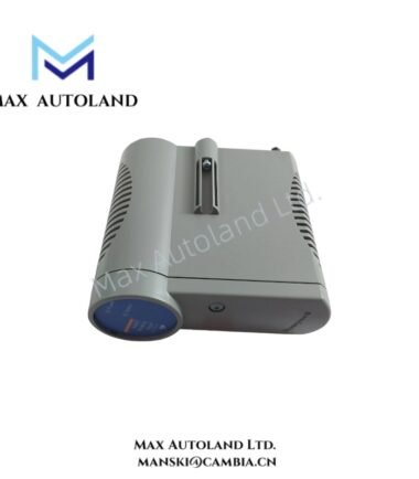
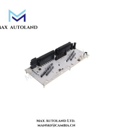
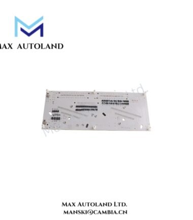
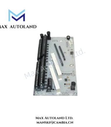
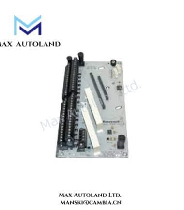
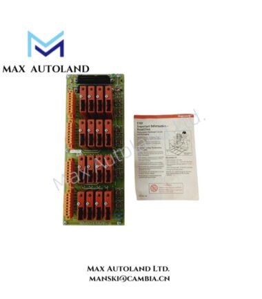
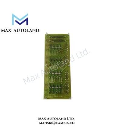
The Honeywell 51303968-100, also cataloged as the 51303968-100 CMOS Battery Backup Assembly, operates as a dedicated hardware component for CMOS memory backup and power monitoring within Honeywell PM/APM platforms.
Hardware Specifications
| Parameter | Specification |
|---|---|
| Model | 51303968-100 |
| Brand | Honeywell |
| Origin | USA (supplier-listed) |
| Weight | 0.1 kg |
| Dimensions | 16.4 x 9 x 3 cm |
| Operating Temp | Standard industrial cabinet range |
| Power Consumption | Powered via backpanel connection |
| Primary Function | CMOS memory backup |
| Secondary Function | Battery charging and monitoring |
| System Compatibility | Honeywell PM/APM platforms |
| Fuse Rating | 0.5 A time-delay fuse |
Process Control Integration and Signal Isolation
The assembly interfaces directly with the Standard Power System chassis backpanel via a dedicated connector to execute continuous battery monitoring and failure alarm reporting. Furthermore, it incorporates channel-to-channel isolation principles to protect the power system chassis from transient voltages while maintaining the stability of the rechargeable NiCad battery system during power fluctuations.
Frequently Asked Questions
Q: Does the 51303968-100 assembly function as a standalone power supply unit?
A: No. It operates exclusively as a dedicated CMOS backup assembly that integrates into the designated backpanel connector of the power system chassis.
Q: How does the module handle failure detection during a power interruption?
A: Integrated monitoring circuitry detects backup-system anomalies and supports direct failure alarm reporting through the power system architecture.
Q: What specific maintenance is required to access the assembly?
A: Accessing the unit in early-production configurations requires the physical removal of the adjacent right-hand Power Supply Module.
Field Installation Guidelines
- Verify the installed power system configuration and confirm the exact connector arrangement before mounting the circuit board.
- Apply strict electrostatic discharge (ESD) precautions by wearing a grounded wrist strap when handling the assembly.
- Inspect the fuse rating and ensure the 0.5 A time-delay fuse is intact prior to system power-up.
- Observe standard manufacturer maintenance procedures when accessing the backpanel connector and securing the module.
- Verify the backup battery voltage and check the associated alarm status indicators after completing installation or replacement.

Reviews
There are no reviews yet.