Overview
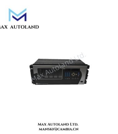
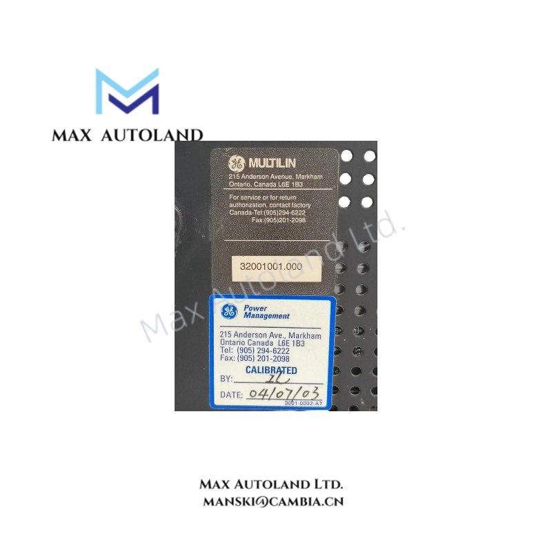
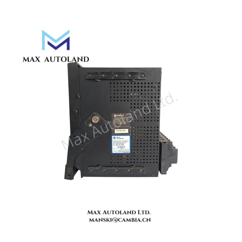
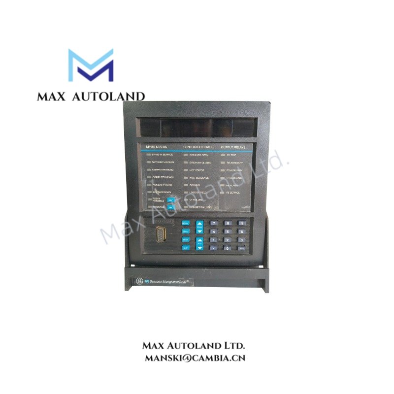
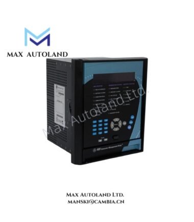
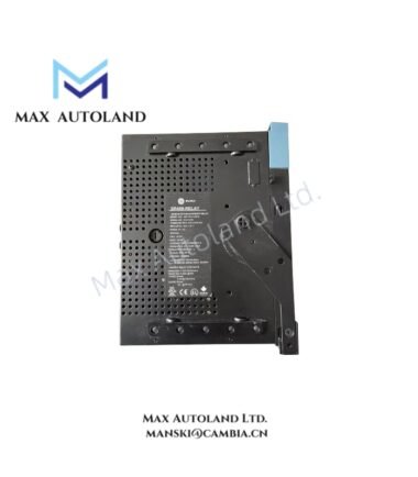
The GE Multilin SR489P5HIA20, also cataloged as the SR489-P5-HI-A20 Generator Management Relay, operates as a dedicated hardware component for phase current monitoring and generator protection logic execution within industrial power generation networks.
Suffix Breakdown & Model Matrix
| Suffix Element | Definition |
|---|---|
| SR489 | 489 Series Generator Management Relay |
| P5 | 5 A Phase Current Transformer Secondary Inputs |
| HI | High Voltage Power Supply Module |
| A20 | Basic Display / Hardware Configuration |
Hardware Specifications
| Parameter | Specification |
|---|---|
| Model Brand | GE Multilin / ABB |
| Origin | North America |
| Weight | 5.00 lbs |
| Dimensions | Standard 1/2 Rack Mount / Panel Cutout |
| Operating Temp | -20 degC to +60 degC |
| Power Supply | 90-300 V DC / 70-265 V AC |
| Frequency Range | 48/62 Hz |
| Phase CT Inputs | 5 A Secondary |
| Analog Outputs | Eight (8) 4-20 mA |
| Display | Basic LCD Display |
Backplane Bus Communication Velocity Licensing
The SR489-P5-HI-A20 utilizes a deterministic internal backplane bus architecture for real-time data exchange between the analog input board and the main processor. Communication velocity is governed by firmware flash compatibility, requiring specific revision matching between the display module and the base unit to prevent data latency during oscillography recording. Profibus DP connectivity is available via optional daughter cards, subject to licensing keys stored in non-volatile memory.
Frequently Asked Questions
Q: Does the SR489-P5-HI-A20 support hot-swap replacement without powering down the generator bus?
A: No. The relay must be de-energized prior to removal or installation to prevent arcing on the terminal blocks and corruption of the onboard EEPROM configuration.
Q: What is the burden impedance for the 5 A phase current inputs?
A: The phase CT inputs present a typical burden of less than 0.2 VA at rated current, compatible with standard 5 A secondary current transformers.
Q: Can the eight 4-20 mA outputs be configured for RTD temperature scaling?
A: Yes. The analog outputs can be mapped to internal thermal model variables, including stator winding temperatures derived from RTD inputs, scaled linearly across the 4-20 mA range.
Field Installation Guidelines
Mount the relay in a panel location that minimizes exposure to high ambient temperatures exceeding 60 degC. Use shielded twisted pair wiring for all 4-20 mA analog output circuits, connecting the shield drain wire to the protective earth at the relay end only. Torque control power terminals to 1.2 Nm. Ensure CT secondary wiring is terminated securely to prevent open-circuit conditions during generator operation.