Overview
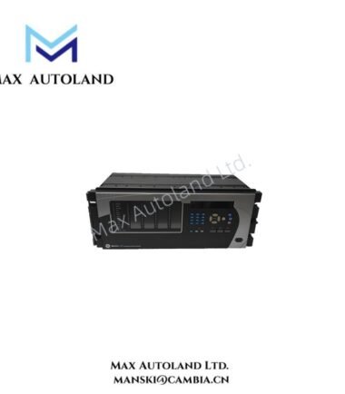
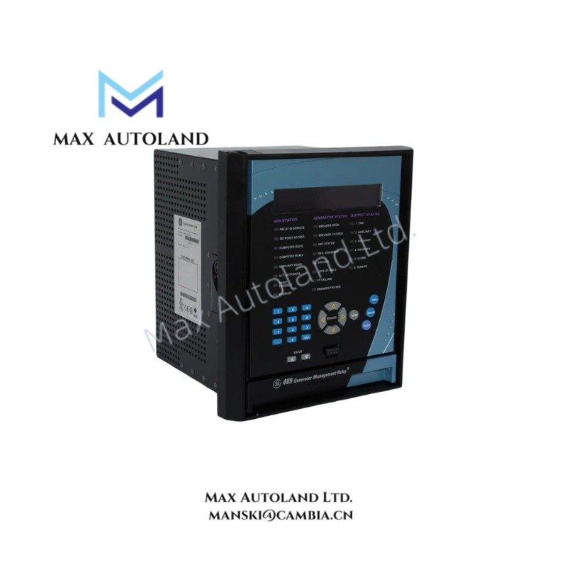
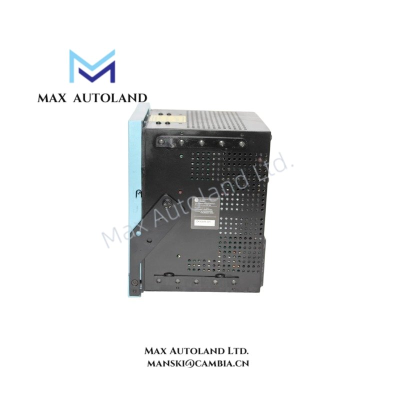
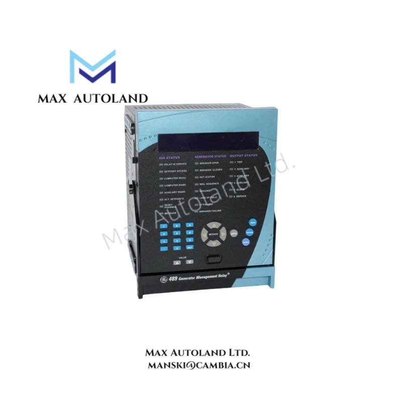
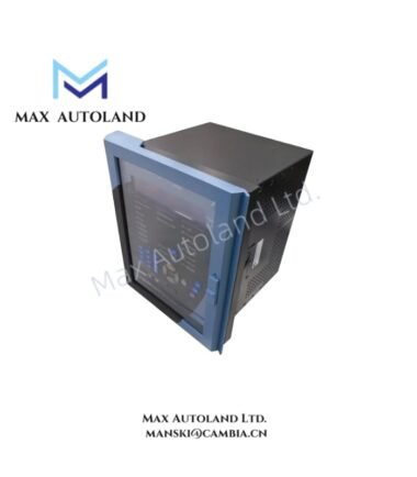
Configured for comprehensive protection and monitoring of small-to-medium synchronous or induction generators, the GE 489-P1-LO-A20-E (base model 489 Generator Management Relay) provides direct physical and electrical execution of protection schemes, metering, and I/O control within generator control systems.
Suffix Breakdown & Model Matrix
| Suffix | Definition |
|---|---|
| 489 | Base Model – Generator Management Relay System |
| P1 | 1 A phase CT secondaries for phase current inputs |
| LO | Low-voltage control power supply (20-60 V DC / 20-48 V AC) |
| A20 | 4-20 mA passive analog current outputs |
| E | Enhanced display with larger LCD and upgraded faceplate navigation |
Hardware Specifications
| Parameter | Specification |
|---|---|
| Model | 489-P1-LO-A20-E |
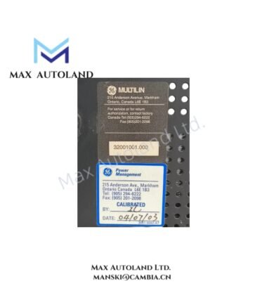
| Brand | GE Multilin |
| Origin | Canada / USA |
| Weight | 17.8 lbs (8.1 kg) |
| Dimensions | Drawout chassis (refer to GE 489 datasheet for exact mm) |
| Operating Temp | -40 degC to +60 degC |
| Power Consumption | Max 45 VA, typical 25 VA |
| Supply Ride-Through | Min 30 ms holdup during supply dips |
| Phase Current Inputs | 3 channels, 1 A CT secondaries |
| Ground Current Input | 1 channel (1 A / 5 A / 50:0.025 HGF CT) |
| Voltage Inputs | 3 channels, up to 275 V AC (Phase-Neutral or Phase-Phase) |
| RTD Inputs | 12 channels (100 Ohm Pt, 100/120 Ohm Ni, 10 Ohm Cu) |
| Digital Inputs | 4 assignable |
| Analog Outputs | 4 channels, 4-20 mA programmable |
| Output Relays | 6 programmable (Trip, Alarm, Auxiliary) |
| Communications | Dual RS485, Modbus RTU, 300-19200 bps |
| Front Interface | RS232 programming port, enhanced LCD, status LEDs |
| IP Rating | Front panel IP40-X |
| Protection Functions | 87G, 51P/G, 50P/G, 51V, 27, 59, 81U/O, 32, 50/27, 95% OV, 100% 3rd harmonic, 40, 46 |
Backplane Bus Communication and Firmware Compatibility
The 489 series utilizes a proprietary GE Multilin backplane communication architecture for integration with GE legacy and modern control platforms. Firmware revisions must be validated against the specific hardware revision level; flash upgrades require the GE Multilin 489 software suite via the front RS232 port. Backward compatibility with older 489 chassis configurations is maintained across firmware branches, provided the hardware suffix matrix matches the ordered feature set.
Frequently Asked Questions
Q: Can the LO power supply version operate on 125 V DC station batteries?
A: No. The LO suffix is limited to 20-60 V DC. For 88-300 V DC or 70-265 V AC applications, the standard or high-voltage power supply suffix must be specified.
Q: Are the 4-20 mA analog outputs isolated from the relay power supply?
A: The A20 configuration provides passive current loop outputs. External loop power supply isolation must be verified per the connected SCADA/DCS analog input card specifications.
Q: Does the E (Enhanced) display support the same communication protocols as the basic version?
A: Yes. The E suffix affects only the front panel hardware (LCD size and navigation). All rear-port communication capabilities (RS485, Modbus RTU) remain identical regardless of display option.
Field Installation Guidelines
- Install the drawout chassis in a standard 19-inch rack or panel cutout per GE 489 mechanical drawings. Terminal wiring remains undisturbed during unit extraction.
- Route CT secondary wiring with separate shielded cables from power and control conductors to minimize induced noise on phase and ground current measurements.
- Connect the LO power supply from a dedicated DC distribution breaker. Verify polarity and voltage level (20-60 V DC) before energizing.
- Ground the relay chassis and shield terminations at a single point to the panel ground bus to prevent ground loops.
- For RTD inputs, use 3-wire configuration where possible to compensate for lead resistance variations across the 12-channel temperature monitoring circuit.
- Terminate RS485 communication cables with proper bias resistors as required by the Modbus RTU network topology. Keep total cable length within RS485 specification limits for the selected baud rate.