Overview
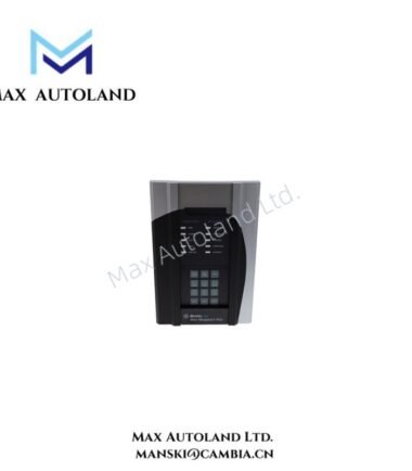
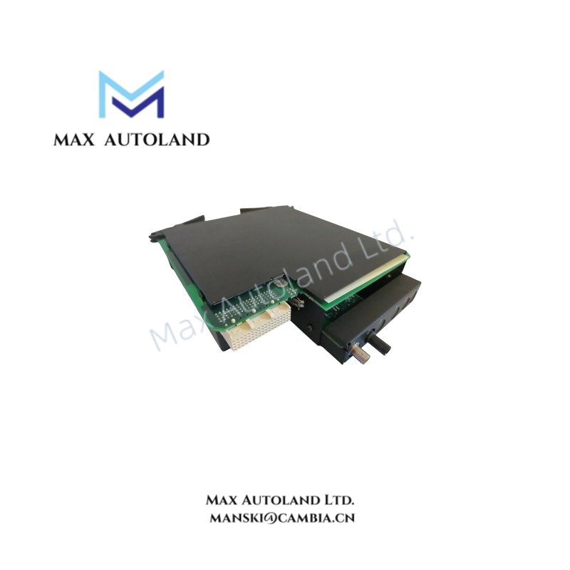
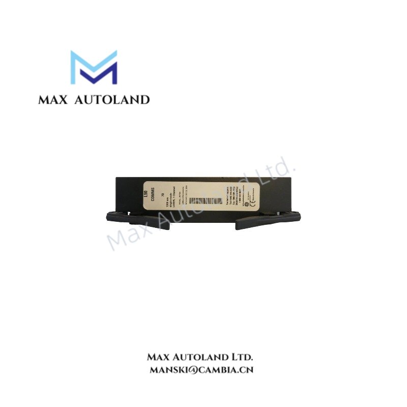
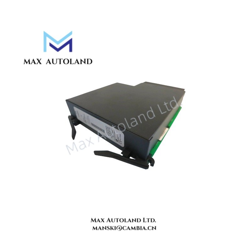
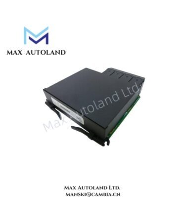
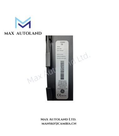
TheGE UR7DH,also cataloged as theUR7DHprotection relay,operates as a dedicated hardware component for high-impedance bus differential fault detection within substation protection and control relay networks. Configured for phase and ground differential measurement, the GE UR7DH (UR7DH) provides direct electrical execution of current comparison logic using stabilized high-impedance CT summation input circuits.
Suffix Breakdown & Model Matrix
No explicit suffix decomposition or order code matrix information is provided in the supplied technical dataset for UR7DH. Configuration-specific parameters are determined by GE Multilin order code selection and hardware slot population.
Hardware Specifications
| Parameter | Specification |
|---|---|
| ModelBrand | GE UR7DH |
| Dimensions | 4RU or 8RU modular chassis (system dependent) |
| OperatingTemp | -40 degC to +60 degC |
| PowerConsumption | Not specified |
| Protection Function | High-impedance bus differential, Restricted Earth Fault (REF) |
| Fault Detection Time | < 1.5 cycles (typical) |
| Sampling Rate | Up to 64 samples per cycle (oscillography) |
| Communications | IEC 61850, Modbus RTU/TCP, DNP3, IEC 60870-5-104 |
| Time Sync | IRIG-B, IEEE 1588 PTP, SNTP |
| I/O Architecture | Modular DI/DO and CT/VT slot-based expansion |
Backplane Communication & Deterministic Control Architecture (GE Industrial Control Binding Feature)
Within the GE Multilin UR platform architecture, internal module synchronization relies on deterministic backplane communication pathways between CPU, protection I/O, and communication modules. Data exchange timing is governed by fixed-cycle scan execution, ensuring consistent sampling alignment across CT/VT acquisition channels during high-speed fault conditions. Firmware image handling supports field upgrade compatibility through controlled flash memory segmentation, minimizing configuration corruption risk during protection logic updates. Communication determinism is maintained across Ethernet-based interfaces, where IEC 61850 GOOSE messaging operates independently from cyclic protection loops to preserve execution latency boundaries.
Frequently Asked Questions
Q: Does the UR7DH support hot-swapping of protection I/O modules?
A: Hot-swapping is restricted for CT/VT input modules. Only communication and certain low-risk digital I/O modules may support live insertion depending on chassis configuration.
Q: How does the relay maintain stability under CT saturation during external faults?
A: Stability is achieved through high-impedance differential architecture, forcing CT secondary voltage balancing and preventing false differential current formation during saturation events.
Q: What is the typical firmware upgrade behavior during protection runtime?
A: Firmware updates are executed via controlled flash overwrite procedure. Protection functions require scheduled downtime as relay logic execution is suspended during image reprogramming.
Field Installation Guidelines
Shielded CT secondary wiring shall be routed with single-point grounding at the relay panel to avoid circulating ground currents. High-impedance differential circuits require equal lead resistance balancing across all CT inputs. Open-circuit CT conditions must be strictly avoided; shorting blocks shall be installed during maintenance. Communication cables for IEC 61850 Ethernet interfaces shall be separated from high-energy switching conductors to reduce induced noise coupling. Terminal torque specifications and rack mounting alignment must follow GE Multilin UR chassis mechanical installation standards.