Overview
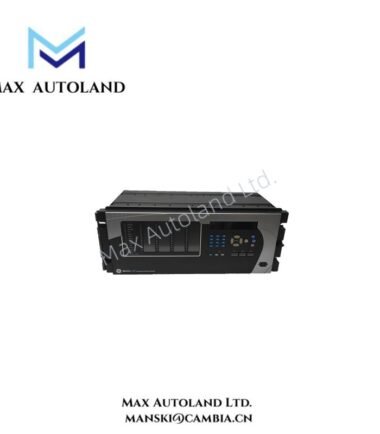
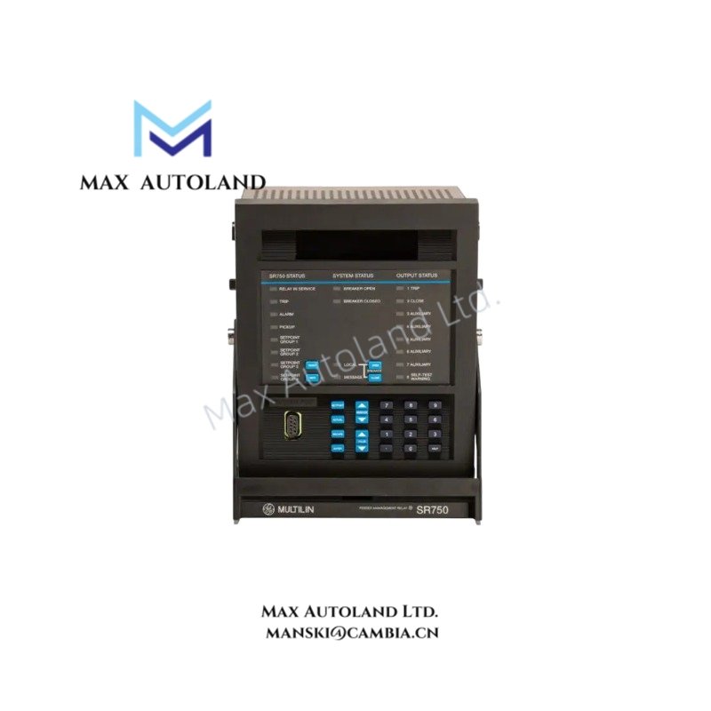
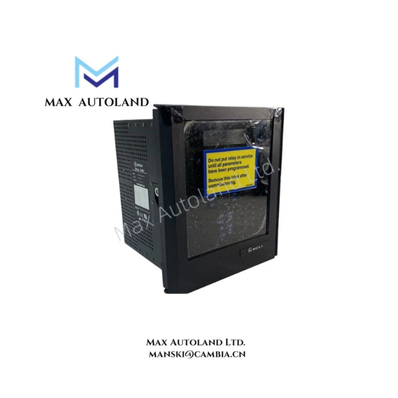
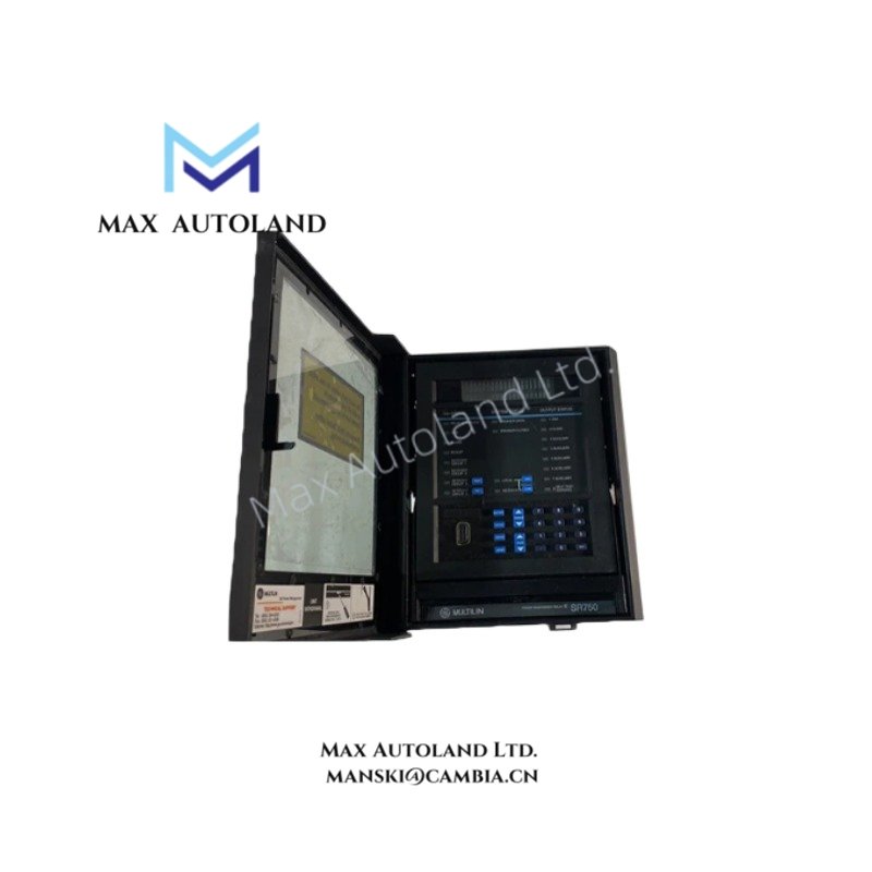
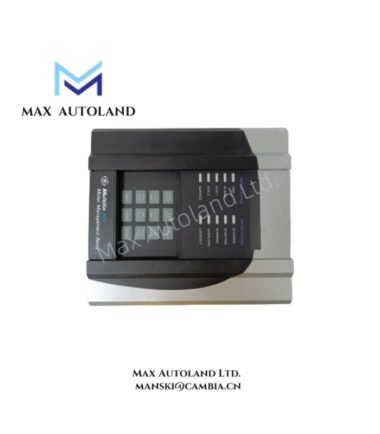
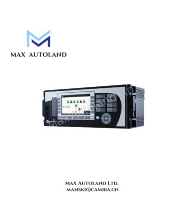
Configured for feeder protection, monitoring, and control in electrical distribution networks, the GE Multilin 750-P5-G1-S1-HI-A20-R (750 Feeder Management Relay) provides direct electrical execution. The unit supports phase, zero-sequence, and sensitive ground current measurement, waveform recording, configurable relay logic, and serial communications for feeder automation and protection functions.
Suffix Breakdown & Model Matrix
The supplied documentation identifies a single configured catalog number. No official suffix decoding or ordering matrix is provided; therefore, individual suffix meanings are not interpreted.
Hardware Specifications
| Parameter | Specification |
|---|---|
| Model | 750-P5-G1-S1-HI-A20-R |
| Brand | GE Multilin |
| Weight | 4.8kg |
| Dimensions | Approx. 180 mm W x 165 mm D x 215 mm H |
| Product Family | GE Multilin 750/760 Feeder Management Relay |
| Phase Current Inputs | 5 A |
| Zero-Sequence Current Input | 1 A |
| Sensitive Ground Current Input | 1 A |
| Control Power | 88-300 VDC; 70-265 VAC, 48-62 Hz |
| Communications Baud Rate | 300 to 19200 baud |
| Frequency | 25-60 Hz nominal |
| Operating Humidity | Up to 90% RH, non-condensing |
| Pollution Degree | II |
| Analog Outputs | Eight 4-20 mA outputs |
| Logic Inputs | Twenty logic inputs; fourteen rear contact inputs |
| Output Relays | Eight electromechanical relays |
| Dedicated Output Relays | Trip Relay 1, Close Relay 2, Self-Test Warning |
| General-Purpose Relays | Five configurable outputs |
| Waveform Capture | 4 current channels, 3 voltage channels, 14 logic input states, 8 output relay states |
| Overvoltage Pickup Level | 0 to 1.25 x VT in 0.01 increments |
| Breaker Status Indicator | Red Breaker Closed LED |
Firmware Flash Compatibility
The relay supports configurable protection logic and parameter storage through its firmware environment. Simulation functions allow testing of relay logic and setpoint behavior without external AC voltage or current injection. Generated simulation values are stored in trace memory for engineering review while maintaining the installed hardware configuration. Firmware updates should be performed only with versions approved for the GE Multilin 750/760 relay platform to maintain configuration compatibility.
Frequently Asked Questions
Q: Does the relay require external current and voltage sources for functional logic testing?
A: No. The relay includes an internal simulation function capable of generating operating values for testing logic, protection settings, and trace memory without external AC current or voltage sources.
Q: Are all output relays user configurable?
A: No. Five electromechanical output relays are configurable for application-specific functions. Three relays are assigned to Self-Test Warning, Close Relay 2, and Trip Relay 1.
Q: Can the rear contact inputs accept both dry and wet contacts?
A: Yes. The fourteen rear contact inputs support either dry or wet contacts and can detect open or closed input states.
Field Installation Guidelines
- Verify that the available control power matches the specified input range before energizing the relay.
- Install current transformer and voltage transformer wiring according to the relay terminal identification to maintain correct phase relationships.
- Route communication cables separately from power conductors to reduce electromagnetic interference.
- Ground cable shields according to the plant grounding standard and avoid multiple shield termination points unless required by the installation specification.
- Confirm output relay assignments and logic input mapping before commissioning protection functions.
- Perform functional testing using the internal simulation capability before connecting the relay to live feeder circuits.