Overview
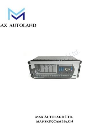
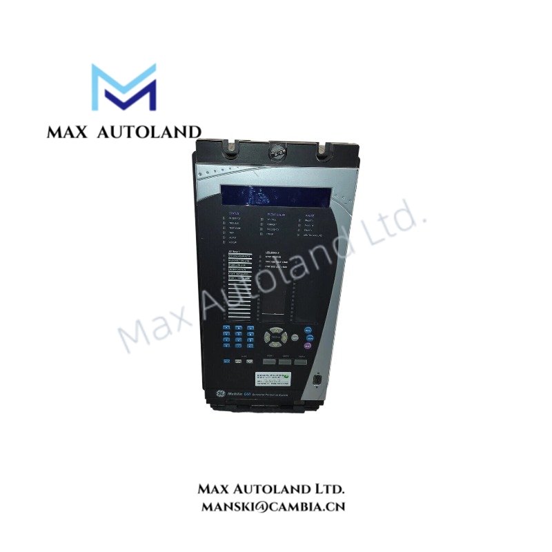
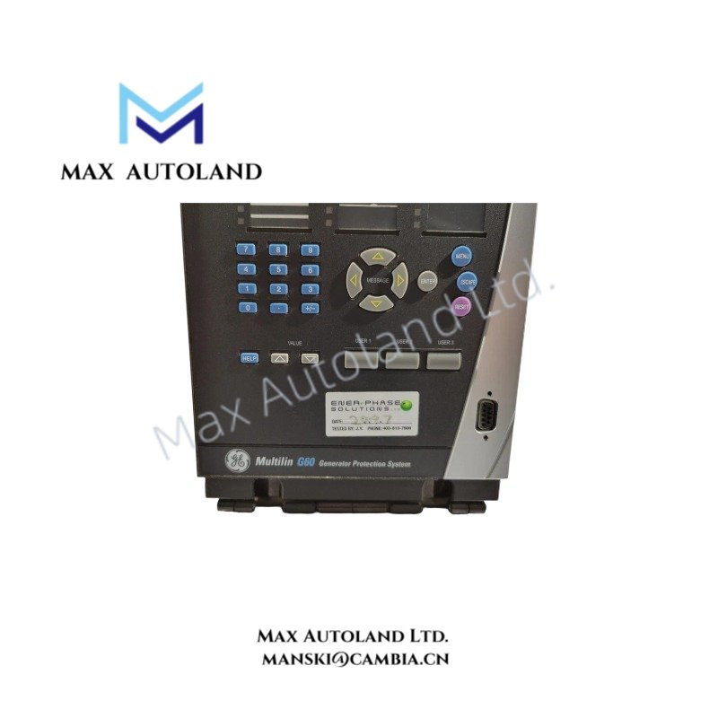
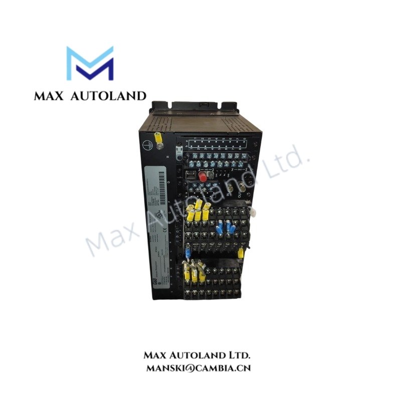
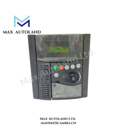
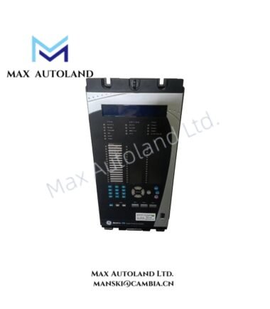
Configured for generator protection, measurement, and control execution in GE Multilin Universal Relay platforms, the GE Multilin G60-G01-HCH-F8F-H67-M8F-P6D-U6D-W6C (G60 Generator Protection System) provides direct electrical processing for generator current, voltage, frequency, and power signals.
Suffix Breakdown & Model Matrix
The provided ordering code G60-G01-HCH-F8F-H67-M8F-P6D-U6D-W6C identifies a specific GE Multilin G60 hardware configuration. The available documentation confirms the following functional sections:
| Code Section | Description |
|---|---|
| G60 | Generator Protection System base model |
| G01 | CPU and standard protection software configuration |
| HCH | High range power supply configuration with AC/DC input capability |
| F8F | Front panel interface with graphical display and control keys |
| H67 | Communication option module supporting Ethernet and serial communication interfaces |
| M8F | Additional communication interface configuration |
| P6D | Digital input/output expansion module configuration |
| U6D | Additional I/O processing module configuration |
| W6C | CT/VT measurement and analog processing configuration |
Hardware Specifications
| Parameter | Specification |
|---|---|
| Model | G60-G01-HCH-F8F-H67-M8F-P6D-U6D-W6C |
| Brand | GE Multilin |
| Origin | Canada |
| Product Type | Generator Protection System |
| System Platform | GE Universal Relay (UR) platform |
| Application | Generator protection, control, metering, and disturbance recording |
| Protection Functions | Generator differential, stator ground, loss of excitation, reverse power, directional power, voltage, frequency, and distance elements |
| Sampling Rate | 64 samples per cycle |
| Power Supply | 110-250 VDC / 120-240 VAC high range supply option |
| Communication Interfaces | RS485, serial, Ethernet 10/100Base-T, 100Base-FX fiber, IEC 61850 |
| Protocol Support | IEC 61850, Modbus RTU/TCP, DNP 3.0, PRP/HSR |
| Enclosure | 19-inch rack mount, 4U height modular chassis |
| Display Interface | Front panel graphical display with control keys |
| Metering Functions | Current, voltage, frequency, real power, reactive power, energy, and power factor |
| Weight | Not specified in available documentation |
| Dimensions | 19-inch rack format, 4U height |
GE Universal Relay Communication and Control Features
The GE Multilin G60 uses the Universal Relay platform architecture to process generator protection signals and execute programmable control logic. The relay supports FlexLogic programming, which allows engineers to configure custom interlocking, trip logic, and automation sequences.
In addition, the communication modules support IEC 61850-based substation networks, serial communication links, and Ethernet data exchange. The relay also supports deterministic network integration through redundant communication options, depending on installed hardware configuration.
The G60 processes CT and VT input signals through dedicated measurement circuits. Therefore, the relay can calculate generator electrical parameters including current, voltage, frequency, active power, reactive power, and power factor.
The system supports I/O density scaling through modular expansion cards. This configuration allows engineers to adapt digital input, digital output, and analog measurement channels according to protection scheme requirements.
Frequently Asked Questions
Q: Does the GE Multilin G60 support hot-swappable module replacement?
A: The G60 uses a modular UR chassis; however, module replacement procedures must follow GE Multilin maintenance instructions. Protection circuits should be placed in a safe maintenance state before hardware removal.
Q: Which communication protocols can the G60-G01-HCH-F8F-H67-M8F-P6D-U6D-W6C support?
A: The configuration supports communication options including IEC 61850, Modbus RTU/TCP, DNP 3.0, RS485, and Ethernet interfaces according to installed communication modules.
Q: How does the G60 handle generator fault recording?
A: The relay records protection events and disturbance waveforms through internal event recording and oscillography functions for fault analysis.
Field Installation Guidelines
- Install the G60 in a suitable 19-inch rack enclosure with proper mechanical support.
- Connect CT and VT wiring according to the protection scheme design and verify polarity before energizing measurement circuits.
- Separate communication cables from high-current power wiring to reduce electromagnetic interference.
- Use shielded communication cables and connect cable shields according to site grounding practices.
- Verify auxiliary power supply polarity before applying AC/DC input voltage.
- Confirm Ethernet and serial communication settings before connecting the relay to the protection network.
- Check digital input voltage levels and output contact wiring before commissioning protection logic.
- Perform functional testing of protection elements, trip outputs, alarms, and communication channels after installation.