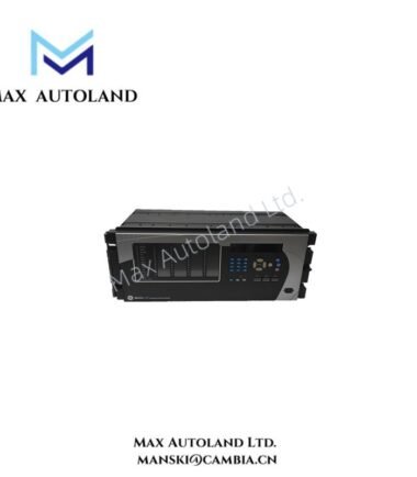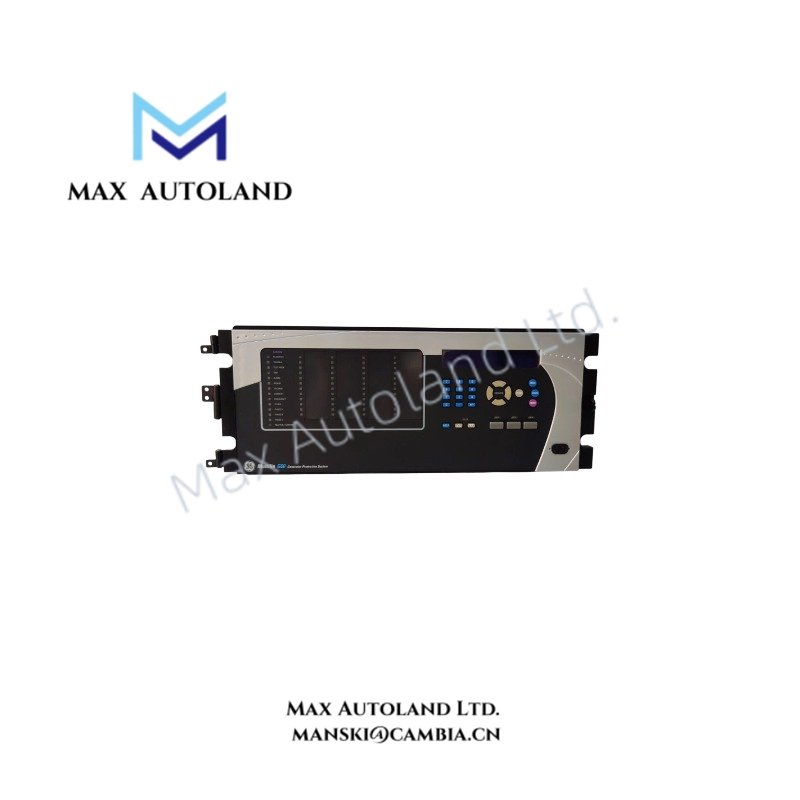
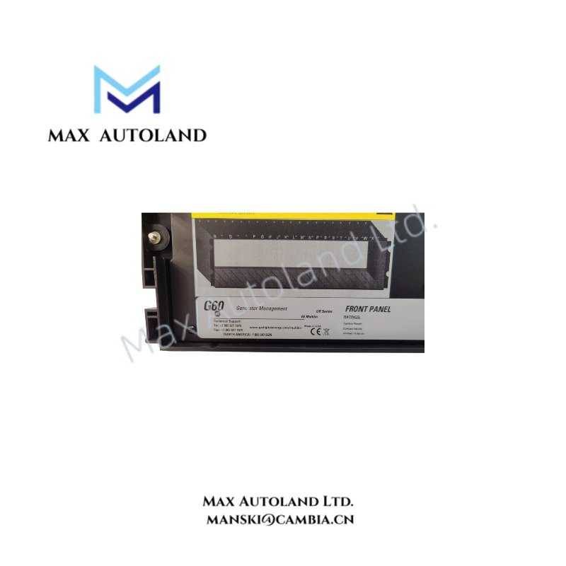
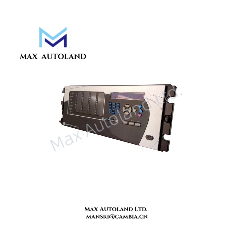
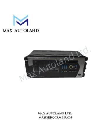
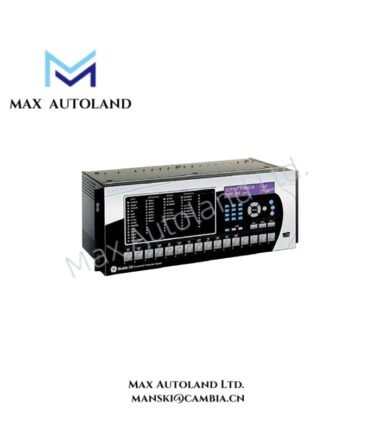
Overview
Configured for generator protection, measurement, and trip control in GE Multilin Universal Relay platforms, the GE Multilin G60-N03-AKH-F8L-H6G-M8L-P67-U67-WXX (G60 Generator Protection Relay) provides direct electrical processing for generator current, voltage, frequency, and protection signals.
Hardware Specifications
| Parameter | Specification |
|---|---|
| Model | G60-N03-AKH-F8L-H6G-M8L-P67-U67-WXX |
| Brand | GE Multilin |
| Origin | Canada |
| Weight | Approx. 5 kg (UR chassis dependent) |
| Dimensions | 4 RU horizontal rack mount chassis |
| Operating Temp | -40 deg C to +60 deg C |
| Power Consumption | <20 W typical, <45 W maximum depending on hardware configuration |
| Product Type | Generator Protection Relay |
| Platform | Universal Relay (UR) Family |
| Power Supply Range | 88-300 VDC / 88-265 VAC, 50/60 Hz |
| Protection Functions | Generator differential, stator ground, distance backup, loss of field, reverse power, overexcitation, frequency protection |
| Communication Interfaces | Ethernet, fiber optic options, RS485 serial |
| Communication Protocols | IEC 61850 GOOSE/MMS, DNP 3.0, Modbus RTU/TCP, IEEE 1588 PTP |
| Logic Control | FlexLogic programmable control engine |
| Mounting Method | Panel or rack mounting |
GE Multilin Generator Protection and UR Platform Functions
The G60 relay processes generator electrical measurements through dedicated CT and VT inputs and applies protection algorithms for synchronous and induction generator applications. In addition, the relay executes high-speed trip decisions through configurable protection logic.
The device provides generator differential protection (87G), stator ground protection, loss of field protection (40), reverse power protection (32), volts per hertz protection (24), and frequency supervision functions (81O/81U/81R). Therefore, the relay can coordinate primary and backup protection schemes within a generator protection system.
The FlexLogic engine allows engineers to configure Boolean logic, timers, interlocks, and custom control sequences without external auxiliary relays. Furthermore, the communication architecture supports IEC 61850 station bus functions, time synchronization, and substation automation integration.
GE Industrial Control Communication and Firmware Compatibility
The GE Multilin G60 uses a modular UR hardware structure that supports configurable I/O expansion and communication modules. The relay exchanges protection and control data through Ethernet-based networks and serial communication channels.
The Universal Relay platform supports firmware flash compatibility for configured hardware assemblies, allowing controlled firmware updates while maintaining application-specific settings. Moreover, the modular backplane design supports I/O density scaling through selectable CT, VT, contact input, output, and communication modules.
Frequently Asked Questions
Q: Does the G60 support IEC 61850 communication?
A: Yes. The G60 supports IEC 61850 GOOSE and MMS communication functions through compatible Ethernet hardware configurations.
Q: What type of mounting arrangement does the G60 use?
A: The G60 uses a 4 RU horizontal rack or panel mounting chassis within the GE Multilin Universal Relay platform.
Q: Can the G60 operate with programmable protection logic?
A: Yes. The relay includes FlexLogic, which allows users to configure protection interlocks, control sequences, and timing functions.
Field Installation Guidelines
- Install the G60 relay inside a suitable protection panel with correct mechanical support for the UR chassis.
- Connect CT and VT circuits according to the approved wiring diagram. Verify polarity, phase sequence, and secondary circuit grounding before energizing the relay.
- Separate communication wiring from high-current power cables to reduce electromagnetic interference.
- Connect Ethernet and RS485 communication shields according to site grounding practices. Avoid multiple unintended grounding points on communication cable shields.
- Verify auxiliary power supply voltage before applying power. Confirm that the selected AC/DC input range matches the installed supply source.
- Perform configuration verification, input testing, trip output testing, and event recording checks before placing the generator protection scheme into service.