Overview
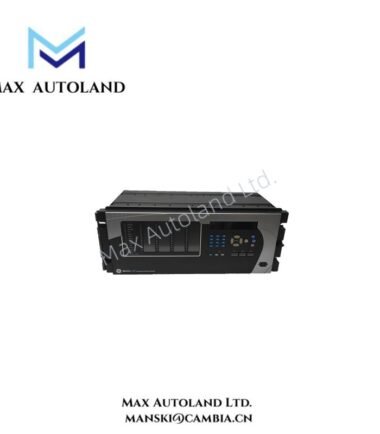
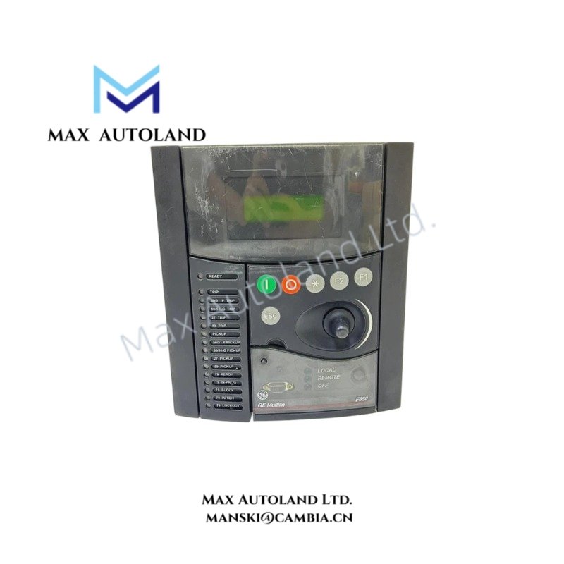
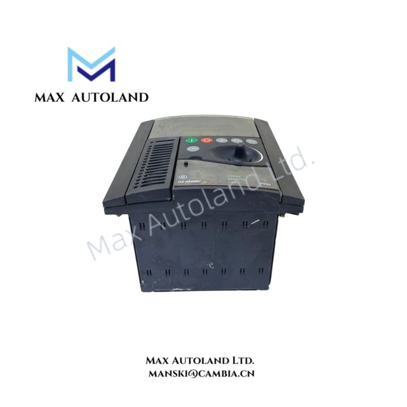
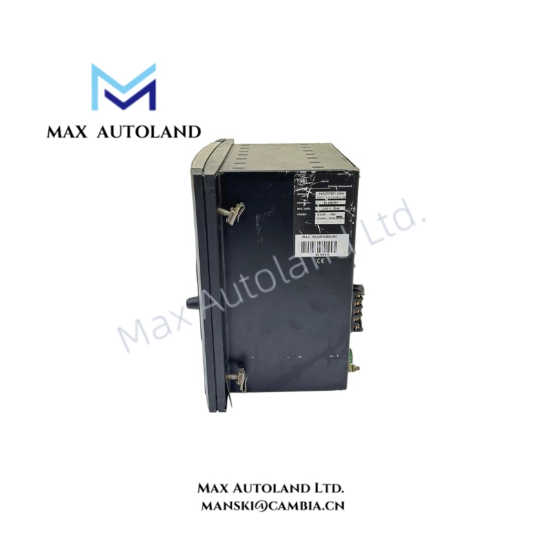
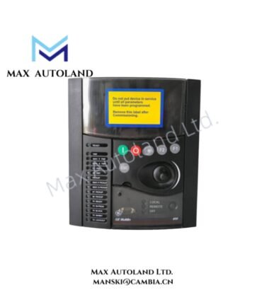
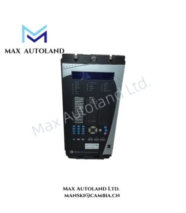
The GE Multilin F650-B-F-M-F-1-G-0-HI-6-E, also cataloged as the F650 Feeder Protection Relay and Bay Controller, operates as a dedicated hardware component for feeder protection, breaker control, and electrical signal processing within substation automation networks.
Hardware Specifications
| Parameter | Specification |
|---|---|
| Model | F650-B-F-M-F-1-G-0-HI-6-E |
| Brand | GE Multilin |
| Origin | GE Multilin F650 Series |
| Product Type | Feeder Protection Relay and Bay Controller |
| Display Interface | Basic alphanumeric LCD display |
| Rear Communication | Ethernet communication interface configuration |
| Communication Protocols | IEC 61850 Edition 2, Modbus RTU, Modbus TCP/IP, DNP 3.0 Level 2, IEC 60870-5-104 |
| Digital Inputs | 16 Digital Inputs |
| Relay Outputs | 8 Relay Outputs |
| Auxiliary Power Supply | 88 to 300 VDC or 96 to 250 VAC |
| Nominal Supply Range | 110 to 250 VDC / 120 to 230 VAC |
| Front Interface | Front USB communication port |
| Protection Functions | Phase overcurrent, ground overcurrent, voltage protection, frequency protection, directional protection |
| Event Recording | Sequence-of-events recording with time stamping |
| Fault Recording | Oscillography and waveform capture |
| Metering Functions | Current, voltage, active power, reactive power, frequency, power factor, energy measurement |
GE Multilin Industrial Control Communication and I/O Architecture
The GE Multilin F650-B-F-M-F-1-G-0-HI-6-E integrates Ethernet communication, programmable logic, and distributed I/O processing for substation automation tasks. The relay exchanges protection data through IEC 61850 Edition 2 messaging and supports GOOSE communication for high-speed interlocking and control applications.
Furthermore, the F650 hardware architecture supports deterministic communication paths between protection elements, breaker control circuits, and external SCADA systems. The integrated I/O expansion configuration provides 16 digital inputs and 8 relay outputs for direct connection to field devices and switching equipment.
The relay processes electrical measurements from current and voltage inputs, then applies protection algorithms including instantaneous overcurrent, time overcurrent, directional elements, and frequency-based load shedding logic. Therefore, it can execute trip commands and control actions based on configured protection settings.
Frequently Asked Questions
Q: Does the F650-B-F-M-F-1-G-0-HI-6-E support IEC 61850 communication?
A: Yes. The model supports IEC 61850 Edition 2 communication, including GOOSE messaging and client/server communication functions.
Q: What digital I/O configuration does this F650 model provide?
A: This configuration includes an I/O board installed in Slot F with 16 Digital Inputs and 8 Relay Outputs.
Q: What auxiliary power input range does the HI power supply option support?
A: The HI auxiliary supply supports 88 to 300 VDC and 96 to 250 VAC input ranges.
Field Installation Guidelines
- Install the GE Multilin F650 relay inside a suitable protective control cabinet with appropriate ventilation and environmental protection.
- Verify auxiliary power polarity and voltage range before energizing the relay.
- Connect communication cables according to the selected Ethernet or serial network architecture.
- Separate protection signal wiring from high-voltage power conductors to reduce electromagnetic interference.
- Use shielded communication and signal cables where required by the substation grounding design.
- Confirm current transformer and voltage transformer wiring polarity before commissioning protection functions.
- Verify digital input contact wiring and relay output circuits before applying trip or breaker control commands.
- Perform configuration validation, communication testing, and protection function checks before placing the relay into service.