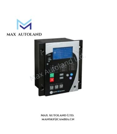
Overview
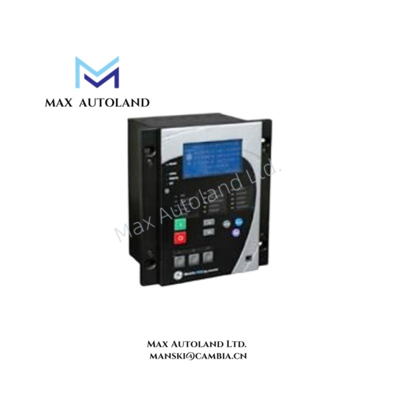
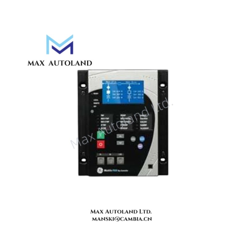
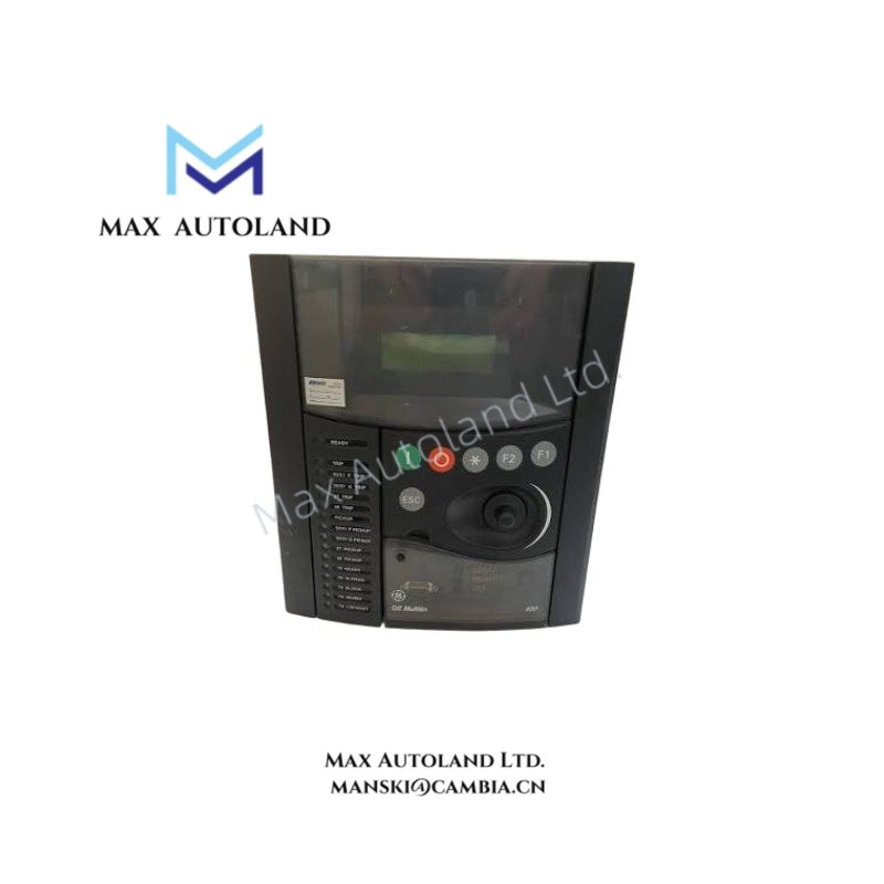
The GE Multilin F650-B-F-E-F-2-G-0-H-I, also cataloged as the F650 Bay Controller, operates as a dedicated hardware component for feeder bay protection, control, and substation automation within electric utility and industrial distribution networks.
Suffix Breakdown & Model Matrix
| Suffix | Designation | Specification |
|---|---|---|
| F650 | Base Model | Multilin F650 Bay Controller & Protection Relay |
| B | Language & Regional Settings | Standard English / International text |
| F | Phase Current Inputs | Standard CT configurations supporting 1A or 5A secondary currents |
| E / F | I/O Board Modules | Dual I/O board modules determining standard allocation of digital input and output channels |
| 2 | Faceplate / HMI Type | Enhanced Graphical LCD Display with customized Single-Line Diagram / Mimic display interface and full local control keys |
| G | Communication Interface | Ethernet and serial communication architecture, providing redundancy option |
| 0 | Rear Connection / Protocol Options | Standard rear connection configuration |
| H | Power Supply Option | High Voltage range: 110-250 VDC / 120-230 VAC |
| I | Environmental Coating | Conformal coating applied to circuit boards for defense against moisture, industrial gases, and dust |
Hardware Specifications
| Parameter | Specification |
|---|---|
| Model | F650-B-F-E-F-2-G-0-H-I |
| Brand | GE – General Electric |
| Origin | Webster, NY, USA |
| Weight | 8 lbs 14.4 oz (4.0 kg) |
| Dimensions | 9.3 in x 10.5 in x 7.3 in (23.5 cm x 26.7 cm x 18.4 cm) |
| Operating Temp | -20 deg C to +60 deg C |
| Storage Temp | -40 deg C to +80 deg C |
| Protection Class | IP54 (panel-mounted from front) |
| Power Consumption | Typical: < 30 W / Max load: 30 VA |
| Input Voltage (H) | 110-250 VDC (+- 20%) / 120-230 VAC (+- 15%) |
| System Frequency | 50 / 60 Hz compatibility |
| AC Current Inputs | Configurable for 1A or 5A secondary loops |
| AC Voltage Inputs | VT connections rated up to 300 V AC phase-to-neutral |
| Digital Inputs | Opto-isolated, programmable threshold 20-300 V DC |
| Output Contacts | High-capacity dry tripping contacts with form-C signal relay outputs |
| Communication Protocols | IEC 61850, DNP 3.0, Modbus RTU/TCP, IEC 60870-5-103/104 |
| Mounting | Standard 4U high enclosure, half-rack or full-rack chassis |
Backplane Communication & I/O Bus Architecture
The F650 utilizes a high-speed internal backplane bus to coordinate data exchange between the protection engine, the embedded PLC processor, and the I/O modules. The backplane architecture supports deterministic scan times for logic execution under IEC 61131-3, ensuring that protection algorithms and control logic operate without mutual interference. The Ethernet communication stack in slot G provides dual-channel redundancy, supporting both RJ45 copper and fiber optic physical layers. Firmware images are flash-upgradable through the front RS232/USB diagnostic port or via the rear Ethernet interface, with version compatibility governed by the hardware revision level of the I/O boards.
Frequently Asked Questions
Q: Can the F650 be hot-swapped while the bay is energized?
A: No. The F650 is not designed for hot-swap operation. Power must be removed from the device before removal or installation. The rear terminal blocks and I/O wiring must be disconnected prior to extracting the unit from the chassis to prevent arcing or contact damage.
Q: What is the maximum switching capacity of the output relay contacts?
A: The tripping contacts are rated for high-capacity interrupting. Refer to the official GE Multilin F650 technical manual for exact VA ratings at specific voltage levels. Exceeding the rated contact capacity will result in weld-failure of the form-C relays.
Q: Does the conformal coating (suffix I) alter the device’s EMC performance?
A: The IEC 61850 compliance and EMC immunity levels remain within the published specifications. The conformal coating is applied exclusively to the PCB substrate to prevent electrochemical migration in high-humidity or corrosive atmospheres and does not degrade signal integrity or conducted emission profiles.
Field Installation Guidelines
- Mounting: Install in a 4U panel cutout with secure mechanical fixing. Verify panel flatness to maintain IP54 sealing integrity at the front bezel.
- Grounding: Connect the chassis ground terminal to the substation earth grid using a minimum 4 mm2 copper conductor. Ensure the shield of all CT and VT leads is grounded at a single point to prevent ground loop currents.
- Wiring: Route CT secondary wiring separately from high-voltage cables and communication cabling. Maintain minimum 50 mm spacing between AC power conductors and low-voltage signal wiring within the panel.
- Ventilation: Do not obstruct the side or rear ventilation paths of the chassis. The unit dissipates up to 30 W continuously; ambient temperature inside the enclosure must be verified not to exceed 60 deg C under worst-case load conditions.
- Commissioning: After installation, verify CT polarity and VT phase sequence using the front panel Mimic display before closing the breaker. Validate all digital input thresholds by applying the field voltage and confirming state change on the HMI.