

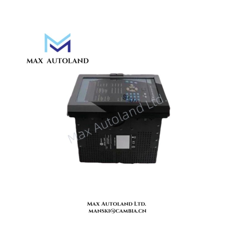


Overview
The GE F650BFEF2G0HIC, also cataloged as the F650 Feeder Protection Relay, operates as a dedicated hardware component for distribution feeder protection, control, and monitoring within electrical substation and industrial automation networks.
Suffix Breakdown & Model Matrix
| Code Segment | Feature Slot | Specification |
|---|---|---|
| F650 | Base Model | Multilin F650 Feeder Protection Relay |
| B | Language | English / French |
| F | Phase CTs | 5A Phase / Neutral CTs |
| E | Ground CT | 1A Ground CT (Sensitive Ground) |
| F | Power Supply | 110-250 VDC / 120-230 VAC |
| 2 | Front Panel | Graphic LCD Display with USB port & Control Keys |
| G | Rear Communications | Ethernet (10/100Base-TX) + RS485 |
| 0 | I/O Card Slot H | None (Empty slot) |
| H | I/O Card Slot I | 16 Digital Inputs + 8 Outputs |
| I | I/O Card Slot J | 8 Digital Inputs + 4 Outputs + 4 Analog I/O |
| C | Harsh Environment | Conformal Coating (Standard Protection) |
Hardware Specifications
| Parameter | Specification |
|---|---|
| Model | F650BFEF2G0HIC |
| Brand | GE (General Electric) |
| Product Type | Feeder Protection and Control Relay |
| Phase CT Input | 5A nominal |
| Ground CT Input | 1A nominal (Sensitive) |
| VT Input | Configurable up to 300 VAC line-to-neutral |
| Power Supply | 110-250 VDC / 120-230 VAC (±20%) |
| Power Consumption | Max 25W |
| Frequency | 50/60 Hz (Auto-setting) |
| Front Panel | Graphic LCD, USB, Control Keys |
| Rear Comms | Ethernet 10/100Base-TX + RS485 |
| I/O Slot H | Empty |
| I/O Slot I | 16 DI + 8 DO |
| I/O Slot J | 8 DI + 4 DO + 4 Analog I/O |
| Operating Temp | -40 deg C to +70 deg C |
| Storage Temp | -40 deg C to +80 deg C |
| Humidity | Up to 95% non-condensing |
| Enclosure Rating | IP54 (Front Panel) |
| Conformal Coating | Standard (Harsh Environment) |
Protection Functions (ANSI Elements)
The F650 supports comprehensive ANSI-standard protection elements:
- Overcurrent: 50P, 50N, 51P, 51N (Timed / Instantaneous)
- Directional Overcurrent: 67P, 67N
- Voltage: 59P (Over), 27P (Under)
- Frequency: 81O (Over), 81U (Under)
- Breaker Failure: 50BF
- Thermal Image: 49
- Synchrocheck: 25
Communication Protocols & Backplane Architecture
The F650BFEF2G0HIC integrates high-speed peer-to-peer communication via IEC 61850 GOOSE messaging over the rear Ethernet port. The device supports Modbus RTU, Modbus TCP/IP, and DNP 3.0 protocols. The rear RS485 serial port provides legacy connectivity for SCADA integration. The front USB port enables local PC configuration and firmware updates without disturbing the live backplane communication.
Frequently Asked Questions
Q: Can the I/O cards in slots H, I, and J be replaced independently?
A: Slots I and J are populated with fixed I/O configurations (16DI+8DO and 8DI+4DO+4Analog respectively). Slot H is empty. I/O cards are not user-replaceable in the field; configuration changes require unit replacement or factory modification.
Q: Does the F650BFEF2G0HIC support hot-swap firmware updates?
A: Firmware updates are performed via the front USB port or rear Ethernet using GE’s configuration software. The device remains operational during firmware download, but protection functions should be considered inactive during the actual flash write cycle. A controlled shutdown of the protected feeder is recommended before firmware updates.
Q: What is the CT burden specification for the 5A phase CT inputs?
A: The F650 phase CT inputs are designed for standard 5A nominal secondary current with burden impedance compatible with typical substation CT configurations. Refer to the GE Multilin F650 instruction manual (publishing number included with unit) for exact burden specifications and CT sizing guidelines.
Field Installation Guidelines
- Mounting: Install the F650 in a standard 19-inch substation rack or panel cutout. Ensure adequate clearance for rear cable terminations and front panel access.
- CT Wiring: Connect phase CT secondaries (5A) to the designated phase inputs. Connect the sensitive ground CT (1A) to the ground input terminal. Verify CT polarity before energization. Short-circuit CT secondaries until the relay is fully connected to prevent dangerous open-circuit voltages.
- VT Wiring: Connect voltage transformer secondaries to the VT input terminals. Maximum input is 300 VAC line-to-neutral. Ensure proper fusing on the VT primary side per local electrical codes.
- Communication Cabling: Use shielded twisted-pair Ethernet cable for the rear Ethernet port. Terminate shield at one end only (preferably at the switch end) to prevent ground loops. For RS485, use 120-ohm characteristic impedance cable with proper termination resistors at both ends of the daisy chain.
- Grounding: Connect the relay chassis ground terminal to the substation ground grid with a minimum 4 AWG copper conductor. The conformal coating (suffix C) provides additional protection but does not replace proper grounding practices.
- Configuration: After mechanical installation, connect a PC to the front USB port. Use GE Multilin software to configure protection settings, I/O mapping, and communication parameters. Validate all settings against the single-line diagram before closing the breaker.