

Overview
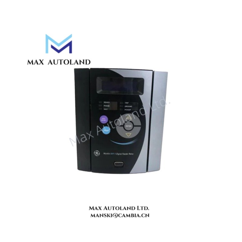
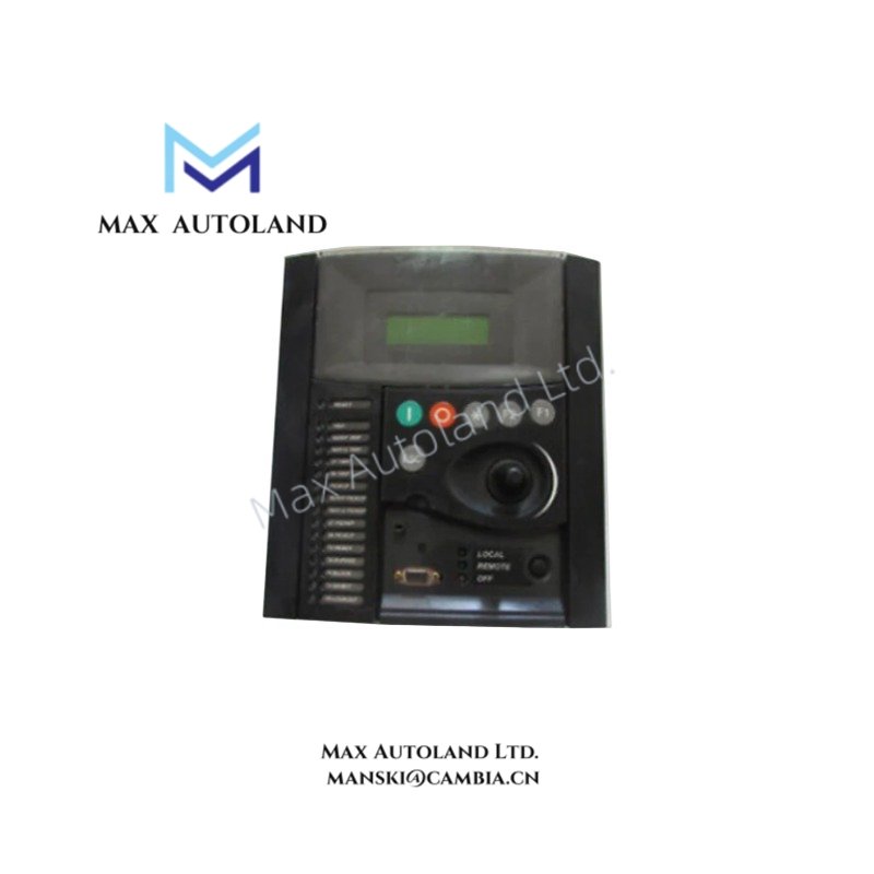
Configured for feeder bay management in substation automation networks, the GE F650BFEF1G0HI (F650 Bay Controller & Protection Relay) provides direct physical execution of breaker tripping, reclosing logic, and analog measurement acquisition.
Suffix Breakdown & Model Matrix
| Code Segment | Definition |
|---|---|
| F650 | Base Model: Multilin F650 Bay Controller & Protection Relay |
| B | Language / Region Variant: Standard English / International |
| F | Phase Current Inputs: 1A or 5A nominal via CT |
| E/F | I/O Board Configuration: Determines digital input and output counts |
| 1 | HMI: Enhanced Graphical LCD with Mimic display and control keys |
| G | Communication: Dual Ethernet (RJ45 or Fiber) and serial interfaces |
| 0 | Rear Connection / Protocol Options |
| H | Power Supply: 110-250 VDC / 120-230 VAC High Voltage Range |
| I | Environmental: Conformal coating for harsh conditions |
Hardware Specifications
| Parameter | Specification |
|---|---|
| Model | F650BFEF1G0HI |
| Brand | GE (General Electric) |
| Origin | Webster, NY, USA |
| Weight | 8 lbs 14.4 oz (4.0 kg) |
| Dimensions | 9.3 in x 10.5 in x 7.3 in (23.5 cm x 26.7 cm x 18.4 cm) |
| Operating Temp | -20 deg C to +60 deg C |
| Power Consumption | 30 W max / 30 VA |
| Power Supply | 110-250 VDC (+/- 20%) / 120-230 VAC (+/- 15%), 50/60 Hz |
| Protection Elements | 50P/51P, 50N/51N, 67P, 67N, 59, 27, 59N, 81O, 81U, 81R, 50BF, 79, 25 |
| Communication Protocols | IEC 61850, Modbus RTU/TCP, DNP 3.0, IEC 60870-5-103/104 |
| Ingress Protection | IP54 (front panel) |
Backplane Bus and Firmware Compatibility
Firmware revisions must match the backplane communication protocol version to ensure deterministic data exchange across the substation network. The device supports flash updates via the front USB port without interrupting rear bus communication. I/O scaling parameters are stored in non-volatile memory and persist through firmware upgrades, eliminating the need for recalibration after updates.
Frequently Asked Questions
Q: Does the F650BFEF1G0HI support hot-swap replacement on a live backplane?
A: No. The device must be de-energized before removal or installation to prevent damage to the rear connectors and ensure correct I/O mapping.
Q: What is the maximum cable length supported for the RS485 rear port?
A: The RS485 interface supports up to 1200 meters when using shielded twisted-pair cabling terminated with 120 ohm resistors at both ends.
Q: Is galvanic isolation provided between the current inputs and the logic circuits?
A: Yes. All current and voltage inputs are galvanically isolated from the internal logic and communication ports to prevent ground loops.
Field Installation Guidelines
Mount the relay in a vertical orientation to allow natural convection cooling. Use M6 bolts torqued to 2.5 Nm for secure panel fixation. Connect the shield of all analog and communication cables to the designated earth terminal only at the relay end to minimize induced noise. Ensure that the conformal-coated PCBs are not exposed to solvents during cleaning, as this may degrade the protective layer.