Overview
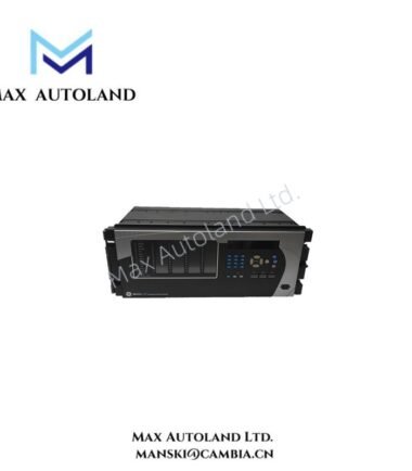
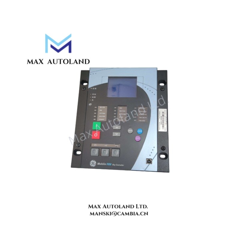
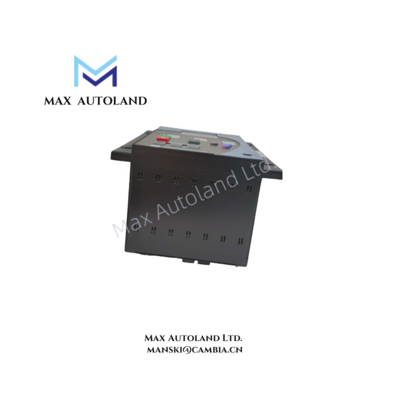
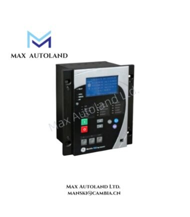
The GE Multilin F650NFLF2G5HIP6E, also cataloged as the F650 Feeder Protection Relay, operates as a dedicated hardware component for directional overcurrent, voltage, and frequency protection within distribution feeder and transformer networks.
Suffix Breakdown & Model Matrix
| Code Segment | Selection | Description / Specification |
|---|---|---|
| F650 | Base Model | Multilin F650 Feeder Protection System |
| N | Language | English |
| F | Phase CTs | 5 A / 1 A (Selectable) Phase Current Inputs |
| L | Ground CT | 5 A / 1 A (Selectable) Ground Current Input |
| F | Voltage Inputs | 3 Phase Voltage Inputs + 1 Auxiliary/Neutral Voltage Input |
| 2 | Power Supply | High Voltage Range: 110 – 250 VDC / 120 – 230 VAC |
| G | Human Machine Interface (HMI) | Graphical LCD Display with Control Keys and Status LEDs |
| 5 | I/O Board 1 (Slot 5) | Standard I/O Board (Typically 8 Digital Inputs + 8 Digital Outputs) |
| H | I/O Board 2 (Slot 6) | Second I/O Board Configuration (8 Digital Inputs + 8 Digital Outputs) |
| I | I/O Board 3 (Slot 7) | Third I/O Board Configuration / Extension |
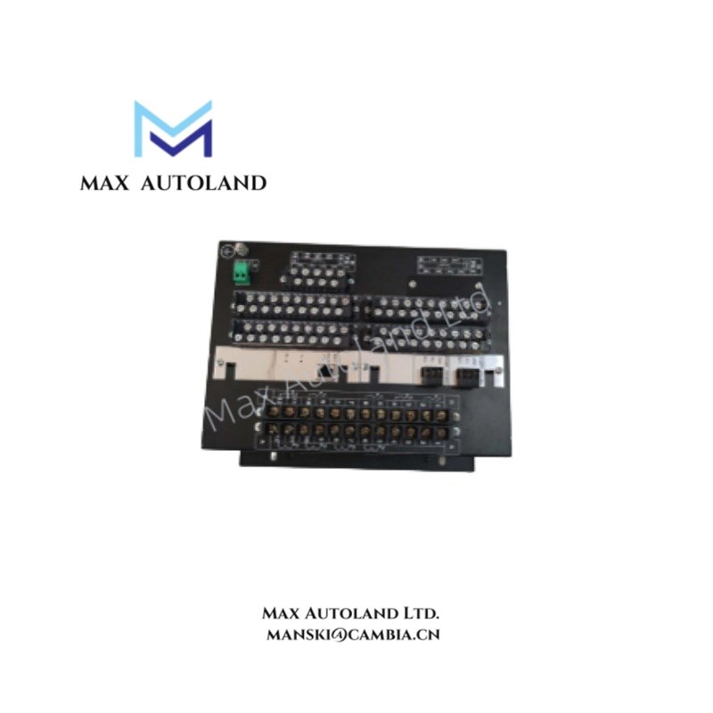
| P | Rear Communications | Ethernet (RJ45 or Fiber) + Serial (RS485/RS232) Ports |
| 6 | Protocols | Advanced Protocols (Includes IEC 61850, Modbus RTU/TCP, DNP3.0) |
| E | Environmental Protection | Harsh Environment Conformal Coating |
Hardware Specifications
| Parameter | Specification |
|---|---|
| Model | F650NFLF2G5HIP6E |
| Brand | GE Multilin |
| Origin | Canada / U.S.A. |
| Weight | Approx. 2.5 kg (Typical for 4U half-rack chassis with options) |
| Dimensions | 4U Half-rack (Horizontal Chassis) |
| Operating Temp | -20 deg C to +60 deg C |
| Power Consumption | Max 25 W (Typical for high-voltage power supply and graphical HMI) |
| Enclosure | Panel or Rack Mounting |
| Protection Class | Conformal Coated (Code E) for harsh environments |
Communication Protocols & I/O Expansion
The F650 series utilizes a backplane architecture allowing for scalable I/O density. The “P” suffix indicates the integration of both Ethernet and serial communication ports on the rear chassis. This hardware configuration supports deterministic data exchange via IEC 61850 MMS and GOOSE messaging, alongside legacy serial protocols such as Modbus RTU. The three I/O boards (configured via codes 5, H, I) provide a total of 24 digital inputs and 24 digital outputs, configurable via the internal FlexLogic(TM) programmable logic engine.
Frequently Asked Questions
Q: What is the maximum sampling rate for oscillography recording on this device?
A: The relay captures up to 64 samples per cycle, storing records of up to 128 cycles per trigger event.
Q: Does the “2” in the suffix support both AC and DC power inputs simultaneously?
A: Yes. The high-voltage power supply module (110-250 VDC / 120-230 VAC) is auto-sensing and supports both sources within the specified range without hardware modification.
Q: Is the Ethernet port on the “P” configuration suitable for fiber optic connectivity?
A: Yes. The “P” designation includes hardware support for both standard RJ45 copper and fiber optic Ethernet connections.
Field Installation Guidelines
- Mounting: Secure the 4U chassis into the designated panel cutout or rack slot using the provided mounting brackets. Ensure the panel is rigid to prevent stress on the rear terminal connections.
- Grounding: Connect the chassis ground terminal directly to the station earth ground bus bar. Use a minimum 4 AWG copper conductor.
- CT Wiring: Verify the polarity of Phase and Ground Current Transformers (CTs) before terminating. Incorrect polarity will cause directional elements (67P, 67G) to operate incorrectly.
- Conformal Coating: Although the unit features a conformal coating (Code E), it should still be installed in a manner that minimizes direct exposure to standing water or conductive dust accumulation.
- Commissioning: After physical installation, verify the voltage input phasing and perform a relay functionality test using primary or secondary injection methods prior to energizing the feeder.