

Overview
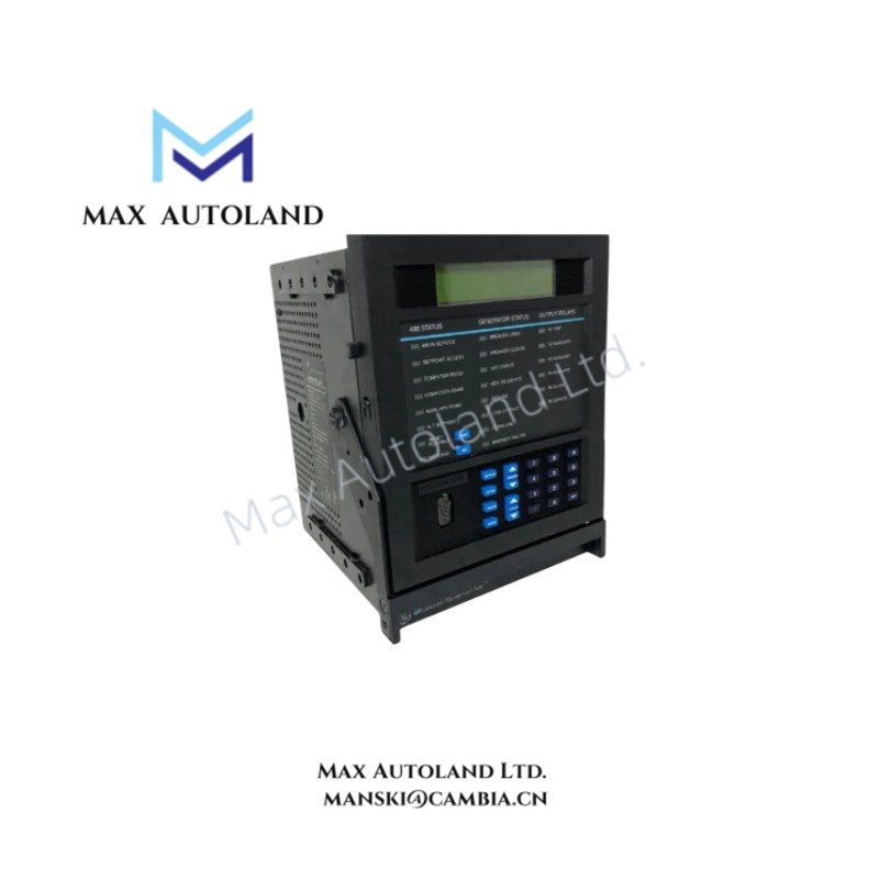
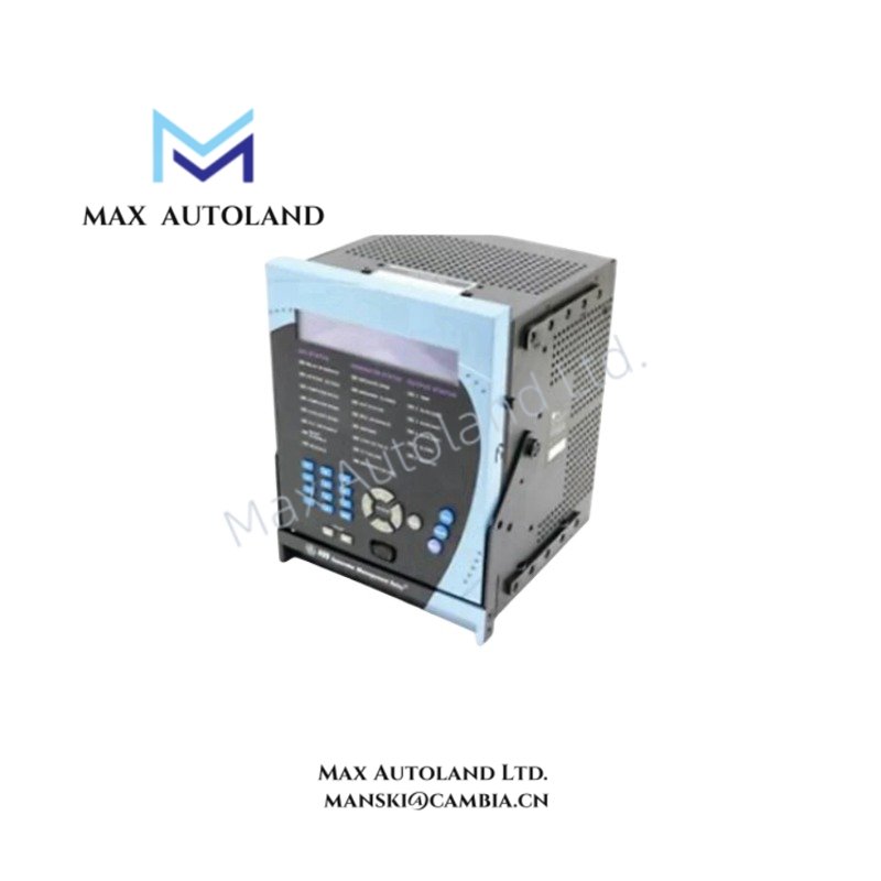
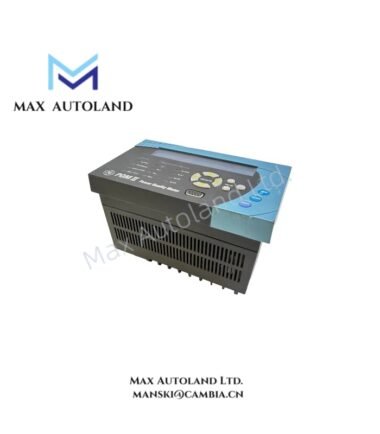
The GE 489-P1-HI-A20-E, also cataloged as the 489 Generator Management Relay, operates as a dedicated hardware component for generator protection, monitoring, and trip execution within generator control and protection systems. The module performs continuous measurement of voltage, current, and frequency while supervising protective functions and control logic.
Suffix Breakdown & Model Matrix
The supplied documentation identifies a single ordering model, 489-P1-HI-A20-E. No official suffix definition or ordering matrix is provided. Individual suffix meanings are therefore not interpreted.
Hardware Specifications
| Parameter | Specification |
|---|---|
| Model | 489-P1-HI-A20-E |
| Brand | GE Multilin |
| Origin | Not specified |
| Weight | 10.76 lbs |
| Dimensions | Not specified |
| Operating Temp | -40 to 60 degC |
| Power Consumption | Not specified |
| Product Type | Generator Management Relay |
| Mounting Method | Panel mounting or 19 in rack mounting |
| Damped Oscillation Test Level | 2.5 kV, 1.0 MHz |
| Ground Overcurrent Curve Shapes | ANSI, IEC, IAC, FlexCurve, Definite Time |
| Dielectric Strength Test | 1.9 kV AC for 1 s or 1.6 kV AC for 1 min per UL 508 |
| Shipping Weight | 7.7 kg (17 lbs) |
| Tachometer Duty Cycle | Greater than 10 % |
| Trip Coil Supervision Trickle Current | 2 to 5 mA |
| Underfrequency Pickup Accuracy | +/- 0.02 Hz |
PLC Communication and Firmware Compatibility
The GE Multilin 489 platform is intended for integration into industrial electrical protection systems where deterministic protection logic operates independently of supervisory communication functions. Firmware maintenance should follow the manufacturer’s documented revision compatibility to preserve protection settings and configuration integrity. Hardware installation should also verify compatibility with the intended panel or 19 in rack mounting arrangement before commissioning.
Frequently Asked Questions
Q: Does the relay support both panel and rack installation?
A: Yes. The published specifications identify support for either panel mounting or installation in a standard 19 in rack.
Q: Can the relay supervise trip circuit continuity?
A: Yes. The relay provides trip coil supervision using a trickle current of 2 to 5 mA as specified.
Q: Is the operating power requirement listed in the available documentation?
A: No. The provided documentation does not specify the input power supply or power consumption. These values should be confirmed from the applicable hardware manual for the exact ordering code.
Field Installation Guidelines
- Verify the ordering code before installation to ensure hardware matches the intended protection scheme.
- Install the relay using the specified panel or 19 in rack mounting method with adequate mechanical support.
- Route current transformer, voltage transformer, and communication wiring separately from high-energy power conductors where practical.
- Terminate cable shields according to the site grounding standard to reduce electrical interference.
- Perform insulation and wiring verification before energizing the relay.
- Confirm protection settings, trip logic, and measurement scaling during commissioning before placing the generator into service.