

Overview
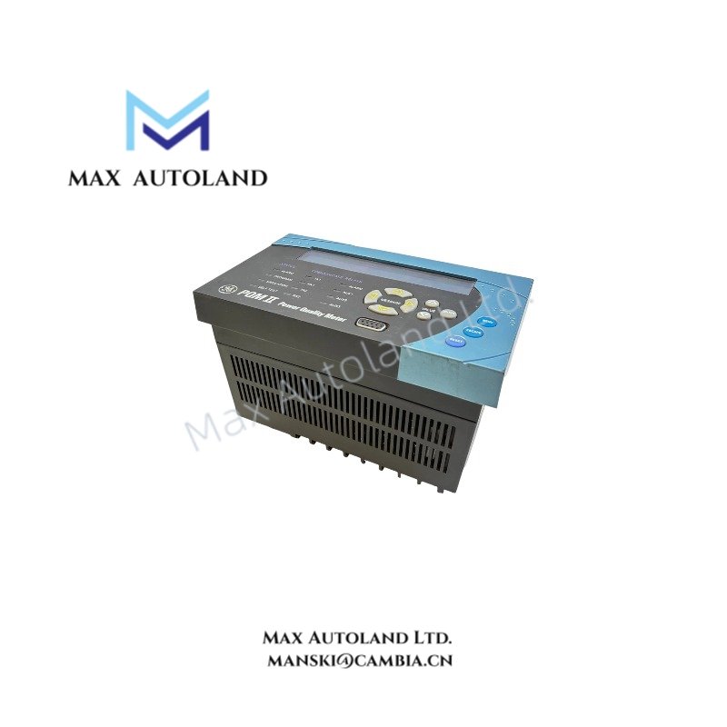
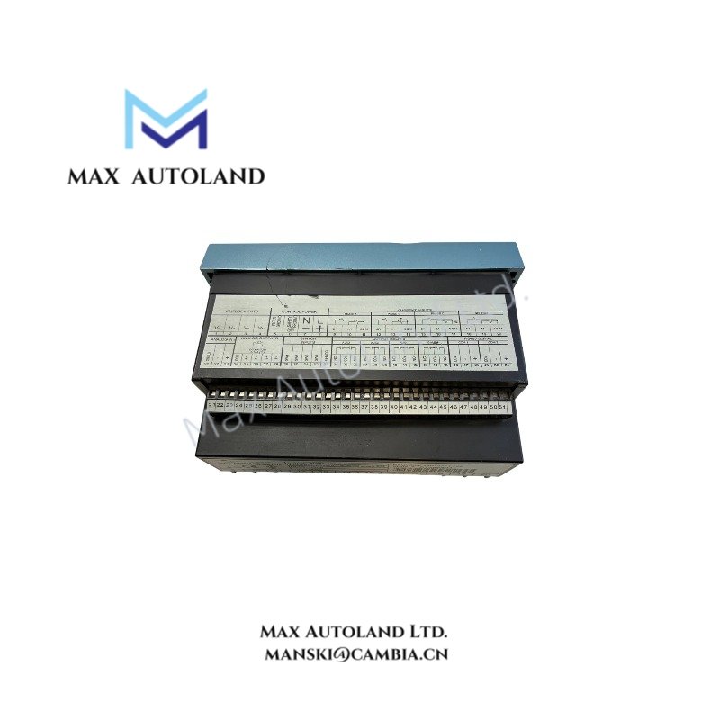
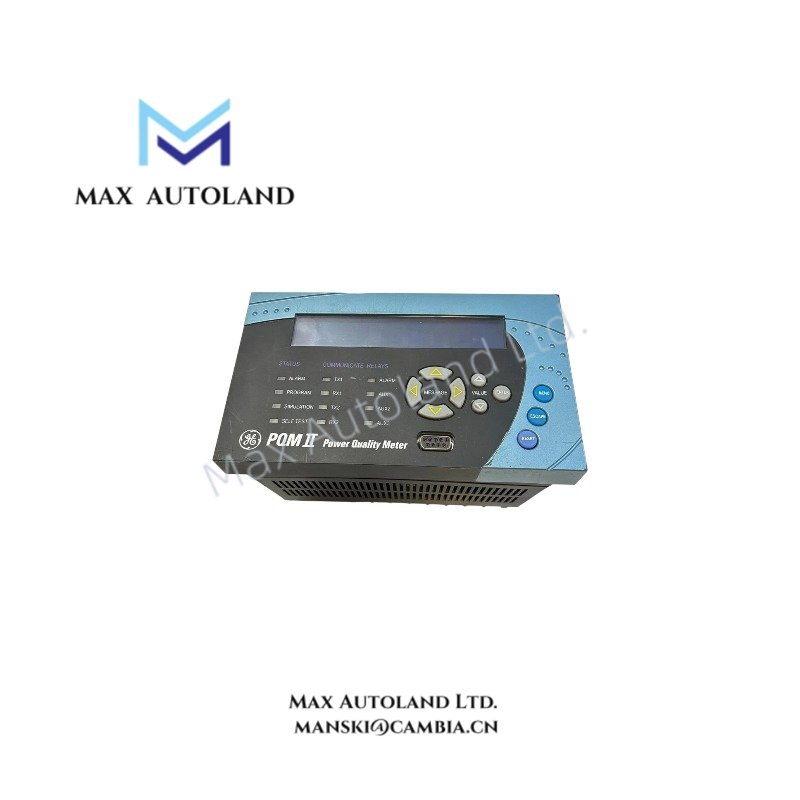
Configured for three-phase power quality measurement and electrical parameter acquisition in industrial power monitoring networks, the General Electric PQMII-T20-C-A (PQMII Power Quality Monitor) provides direct physical and electrical execution. The PQMII-T20-C-A integrates voltage, current, analog, digital, relay, and serial communication interfaces for continuous monitoring and control functions.
Suffix Breakdown & Model Matrix
The supplied documentation identifies a single catalog number, PQMII-T20-C-A. No official suffix decoding or model matrix is provided in the available manufacturer information; therefore, no suffix interpretation is included.
Hardware Specifications
| Parameter | Specification |
|---|---|
| Model | PQMII-T20-C-A |
| Brand | General Electric |
| Product Type | Power Quality Monitor |
| Origin | USA |
| Place of Shipment | Xiamen, China |
| Dimensions | 18.7 x 12.5 x 11 cm |
| Weight | 1.46 kg |
| Operating Temp | -25 degC to +70 degC |
| Storage Temp | -40 degC to +85 degC |
| Humidity | 5 % to 95 % RH, non-condensing |
| Power Supply | 20 – 60 VDC or 20 – 48 VAC |
| Frequency | 45 – 65 Hz (measurement), 50/60 Hz (power input) |
| Power Consumption | 20 VA |
| Voltage Measurement | Three-phase |
| Current Inputs | 5 A or 1 A secondary CT inputs |
| Analog Input | One 4 – 20 mA input |
| Relay Outputs | Four output relays |
| Digital Inputs | Four switch inputs |
| Analog Outputs | Four isolated analog outputs |
| Setpoints | Configurable for alarm or control |
| Communication Ports | Two rear RS-485 Modbus ports, one front RS-232 port |
PLC Communication and Firmware Compatibility
The PQMII platform exchanges process data through Modbus serial communication using two rear RS-485 interfaces and one front RS-232 service interface. System integration depends on compatible Modbus register mapping within the supervisory controller or SCADA host. Firmware compatibility should be verified before applying configuration files or restoring archived settings between different hardware revisions.
Frequently Asked Questions
Q: Does the PQMII-T20-C-A support both 1 A and 5 A current transformer secondary inputs?
A: Yes. The unit accepts either 1 A or 5 A CT secondary inputs as specified by the connected measurement system.
Q: Can the relay outputs be assigned to alarm functions?
A: Yes. The four relay outputs support configurable setpoints for alarm indication or control functions according to the device configuration.
Q: Are all analog outputs electrically isolated?
A: Yes. The available documentation specifies four isolated analog outputs.
Field Installation Guidelines
- Verify that the incoming supply voltage matches the specified 20 – 60 VDC or 20 – 48 VAC operating range before energizing the device.
- Connect current transformer secondary circuits according to standard CT wiring practices and never leave energized CT secondary terminals open during installation or maintenance.
- Route analog signal wiring separately from high-voltage power conductors to reduce conducted electrical noise.
- Use shielded twisted-pair cable for RS-485 communication and terminate the network according to the Modbus serial network design.
- Connect cable shields and protective grounding in accordance with the facility grounding practice to minimize communication interference.
- Confirm relay, analog output, and switch input wiring against the configured I/O assignments before commissioning.