Overview
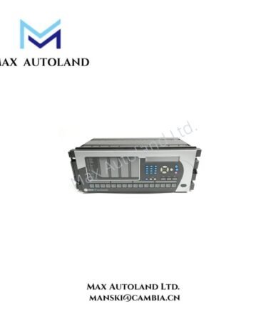
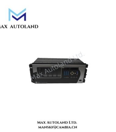
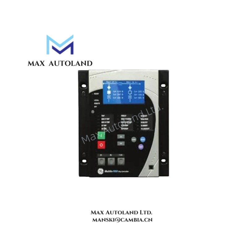
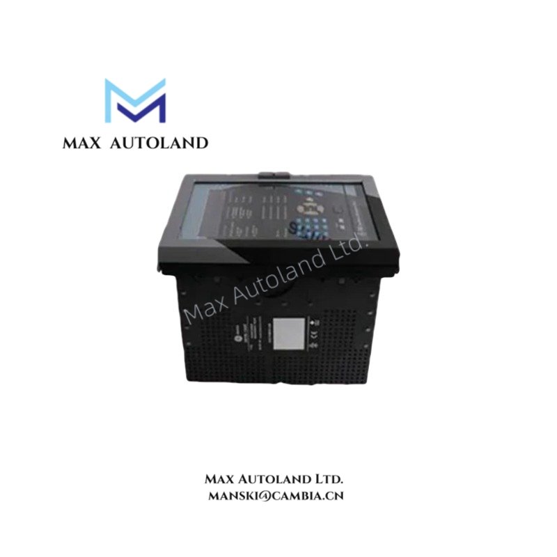
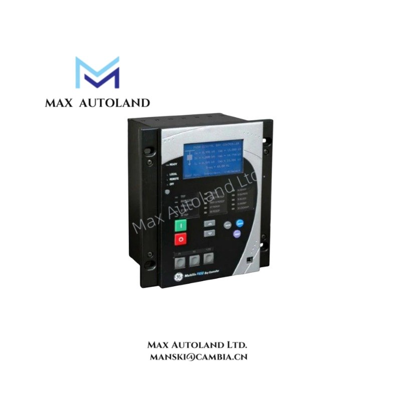
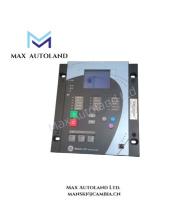
Configured for feeder protection in substation networks, the GE F650BABF1G0HLO (F650 Feeder Protection Relay) provides direct physical execution of overcurrent, directional, and voltage protection schemes while integrating metering and communications functions.
Suffix Breakdown & Model Matrix
| Position | Code | Definition |
|---|---|---|
| Base | F650 | Feeder Protection System |
| Option 1 | B | Phase CT (1 A / 5 A programmable), Neutral CT (1 A / 5 A programmable), Sensitive Ground CT (0.1 A – 2 A) |
| Option 2 | A | Standard Voltage Inputs (0 – 230 V) |
| Option 3 | B | Standard Display / HMI with Text and Control Keys |
| Option 4 | F | Dual Rated Power Supply (24 – 48 VDC) |
| Option 5 | 1 | Standard I/O (16 Digital Inputs, 8 Outputs) |
| Option 6 | G | Standard Communications (RJ45 Ethernet, RS485 / RS232) |
| Option 7 | 0 | No Redundant Communications |
| Option 8 | H | Standard Protocol Package (Modbus RTU, Modbus TCP/IP, DNP 3.0) |
| Option 9 | L | Enhanced Logic, Metering, and Fault Recording |
| Option 10 | O | IEC/ANSI Regional Defaults |
Hardware Specifications
| Parameter | Specification |
|---|---|
| Model | F650BABF1G0HLO |
| Brand | GE Multilin |
| Origin | Canada / Mexico |
| Weight | Approx. 2.5 kg |
| Dimensions | 4U Height, 1/2 19-inch Rack Width |
| Operating Temp | -20 deg C to +60 deg C |
| Power Consumption | < 15 W typical (24 – 48 VDC supply) |
| Current Inputs | 1 A / 5 A Nominal (Software Configurable) |
| Voltage Inputs | 0 – 230 VAC Line-to-Neutral |
| Front Panel Rating | IP54 (with gasket) |
| Rear Case Rating | IP20 |
Backplane Bus and Firmware Compatibility
Firmware revisions must match the installed hardware version to ensure proper backplane bus communication velocity licenses. The F650 utilizes a deterministic internal bus for high-speed data exchange between the CPU and I/O modules. Configuration files created in EnerVista software require verification against the relay’s firmware build number prior to download. Incompatible firmware loads may result in I/O scaling errors or failure to recognize optional hardware configurations.
Frequently Asked Questions
Q: Does the F650 support hot-swap replacement without de-energizing the control circuit?
A: No. The power supply and I/O terminals must be de-energized before removing or inserting the relay. Hot-swap operation is not supported due to live rear terminal connections.
Q: What is the maximum sampling rate for oscillography records?
A: The relay captures up to 64 samples per cycle, providing 64-cycle records for detailed transient analysis.
Q: Are the digital inputs compatible with both wet and dry contact sources?
A: Yes. The digital inputs are software-configurable for wet (externally powered) or dry (relay-powered) contact operation.
Field Installation Guidelines
Mount the relay in a vertical orientation using the provided panel cutout dimensions. Ensure the gasket is properly seated to maintain the IP54 front panel rating. Terminate all AC current and voltage wiring using crimped ring lugs tightened to the torque values specified on the relay housing label. Shielded twisted-pair cables must be used for RS485 communications; connect the shield drain wire to the designated ground terminal only at the relay end to prevent ground loops. Verify the gap between the relay case and enclosure door does not impede ventilation.