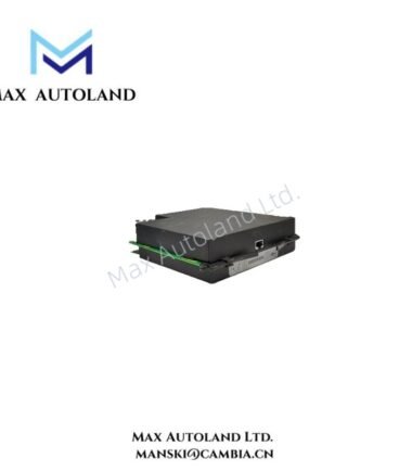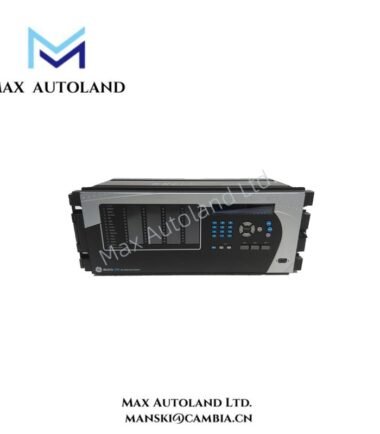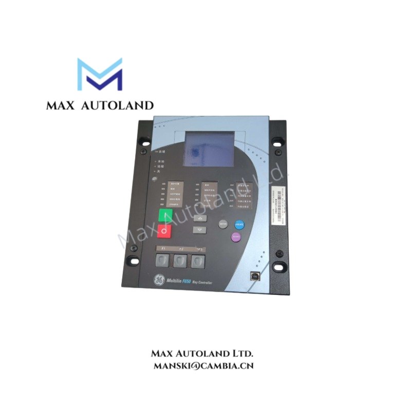
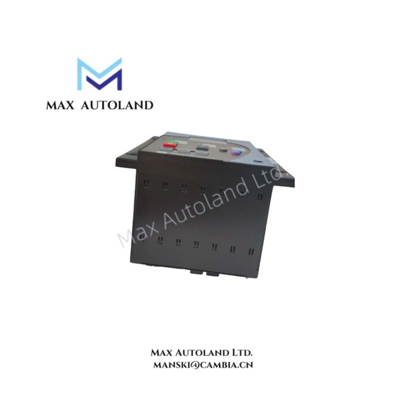
Overview
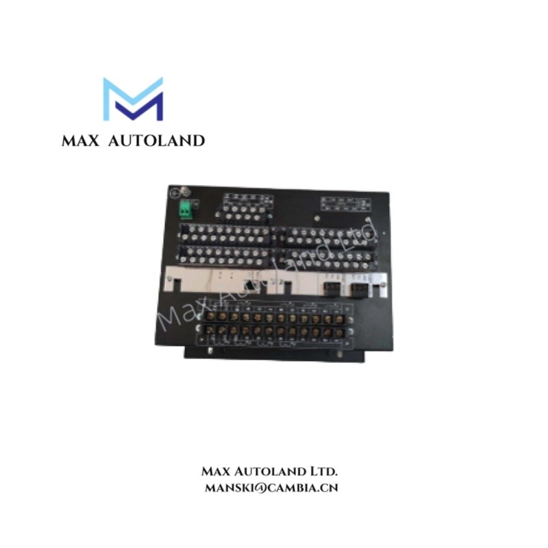
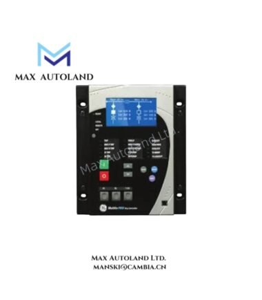
Configured for motor protection in industrial power systems, the GE 369-HI-R-M-0-0-H-E (369 Series Motor Management Relay) provides direct physical execution of thermal overload algorithms and phase current differential calculations. It processes analog inputs from current transformers and outputs discrete trip signals to circuit breaker coils.
Hardware Specifications
| Parameter | Specification |
|---|---|
| Model | 369-HI-R-M-0-0-H-E |
| Brand | GE Multilin |
| Origin | Webster, NY, USA |
| Weight | 8 lbs 14.4 oz (4.0 kg) |
| Dimensions | 9.3 in x 10.5 in x 7.3 in (23.5 cm x 26.7 cm x 18.4 cm) |
| Operating Temp | -20 deg C to +60 deg C |
| Power Consumption | < 15 VA @ 120 VAC |
| Communication Ports | RS-485 (Modbus RTU) |
Firmware Flash Compatibility
The unit supports firmware flash upgrades via the front serial port to maintain backward compatibility with legacy GE Multilin 369 series configurations. Backplane bus communication velocity is governed by the internal processor clock and remains fixed at 19.2 kbps for Modbus slave operations. I/O density scaling is managed through the relay’s onboard configuration registers, allowing mapping of up to 12 digital inputs to specific protection functions without requiring external logic solvers.
Frequently Asked Questions
Q: Does the 369-HI-R-M-0-0-H-E support hot-swap replacement on a live backplane?
A: No. The relay must be de-energized prior to removal or installation to prevent arcing on the terminal blocks and corruption of non-volatile memory.
Q: What is the typical backup time for the internal real-time clock during power loss?
A: The internal supercapacitor maintains clock integrity for a minimum of 72 hours when operating within the specified temperature range.
Field Installation Guidelines
Mount the relay in a vertical orientation to align with convection cooling paths. Torque control power terminals to 1.2 N·m (10.6 lb-in). Shielded twisted pair cabling is mandatory for CT inputs; ground the shield drain wire at the relay end only. Ensure a minimum clearance of 50 mm above and below the device for adequate airflow.