Overview
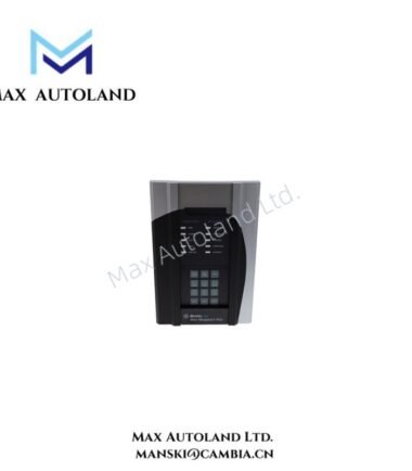
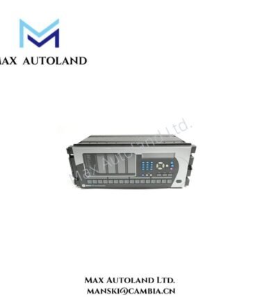
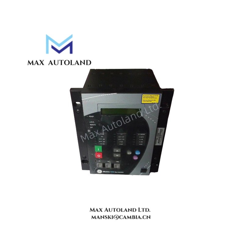
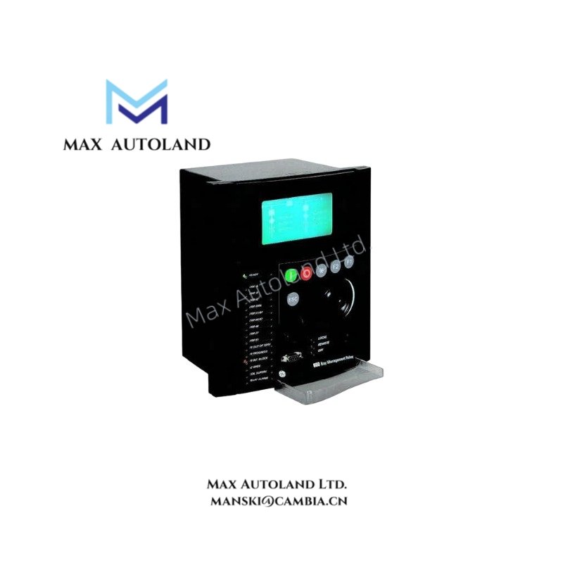
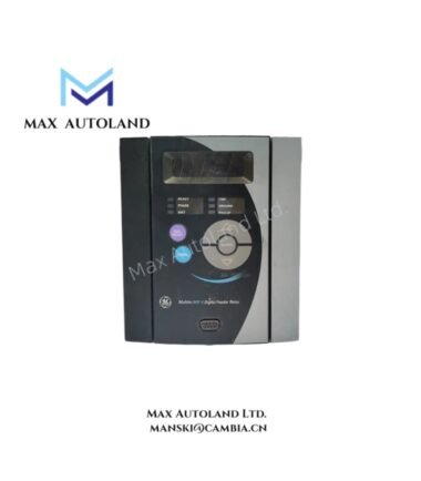
The GE Multilin F650BFBF1G0HICE, also cataloged as the F650 Feeder Protection and Bay Controller Relay, operates as a dedicated hardware component for distribution feeder protection, control, metering, and automation within utility and industrial substation networks.
Suffix Breakdown & Model Matrix
| Suffix/Code | Description |
|---|---|
| F650 | Base model for Feeder Protection/Bay Control |
| 1G / G0 | Standard analog/current input configurations |
| HI | High-voltage universal power supply module (110-250 VDC / 100-240 VAC) |
| C / E | Communication protocol variants (Modbus/DNP3, Ethernet capability, front USB) |
Hardware Specifications
| Parameter | Specification |
|---|---|
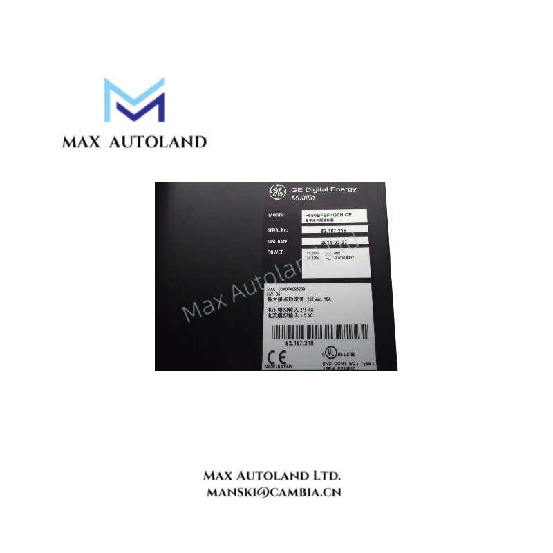
| Model | F650BFBF1G0HICE (F650-BF-BF1-G0-HI-C-E) |
| Brand | GE Vernova (formerly GE Multilin) |
| Function Class | Feeder Protection and Bay Management Controller |
| Power Supply | 110-250 VDC / 100-240 VAC (wide-range auxiliary) |
| Analog Inputs | Phase CTs: 1 A / 5 A (software selectable); Neutral CT: 1 A; VT Range: 0-250 V AC |
| Digital I/O | 16 contact inputs; 8 Form-A/B outputs; 4 latching control outputs |
| Protection Elements | 50P/51P, 50G/51G, 50N/51N, 59/27, 81O/81U, 50BF, 25, 79 (4-Shot Autoreclose) |
| Metering Accuracy | Revenue-grade energy calculation (Class 0.2s); +/-0.2% on current and voltage vectors |
| Monitoring & Recording | COMTRADE oscillography (64 samples/cycle); Event recorder (1024 entries, 1 ms resolution) |
| Communications | 2 x RS485 (Modbus RTU / DNP3.0); Rear Ethernet; Front USB |
| Operating Temp | -40 deg C to +70 deg C (-40 deg F to 158 deg F) |
| Enclosure / Mounting | Draw-out or fixed chassis options; IP54 front panel protection |
Backplane Bus Communication and I/O Scaling
The F650 series utilizes a high-velocity backplane bus architecture to manage data exchange between the protection engine and the bay controller logic. The I/O density scales to accommodate high-count discrete input requirements (16 channels) directly on the base unit, eliminating the need for external expansion modules in standard feeder bay deployments. Firmware flash compatibility is maintained across the F650 series, allowing field upgrades via the front USB port or rear Ethernet interface without removing the unit from the chassis.
Frequently Asked Questions
Q: Does the F650 support hot-swap functionality in a live rack?
A: No. The F650 is designed as a draw-out unit but must be mechanically isolated and withdrawn from the chassis before removal. The backplane connections are not rated for live hot-swap insertion.
Q: What is the typical backplane power consumption for system budgeting?
A: The device draws approximately 15 W under normal operating conditions with all I/O active. System designers should allocate a minimum 24 VDC auxiliary supply margin of 30 W to account for contactor coil inrush during control output switching.
Q: Is the Ethernet port suitable for direct connection to a wide-area network (WAN)?
A: The rear Ethernet interface is intended for substation-local area network (LAN) integration. It does not possess hardware-level firewalls; therefore, it should be isolated behind a managed switch or gateway when connecting to external networks.
Field Installation Guidelines
- Mounting: Install the relay in a standard 19-inch substation rack or panel cutout. Ensure the chassis is securely fastened to prevent vibration-induced loosening of the backplane connectors.
- Grounding: Connect the chassis ground terminal directly to the substation earth grid using a minimum 4 AWG copper conductor. Proper shielding and grounding are critical to prevent noise interference with the analog voltage and current inputs.
- Wiring: Use shielded twisted pair (STP) cables for all CT and VT connections. Keep control wiring (digital I/O) separated from high-voltage power cables to maintain signal integrity and reduce the risk of inductive coupling.
- Torque: Tighten all terminal block screws to the manufacturer’s specified torque values (refer to the official GE instruction manual for exact Nm/lb-in values) to ensure long-term contact reliability.