




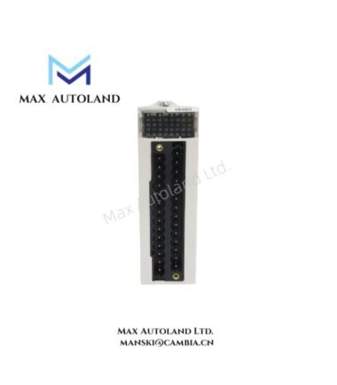
Overview
The GE Multilin MIFIIPI11E10HI00, also cataloged as the MIF II Digital Feeder Relay, operates as a dedicated hardware component for three-phase and ground overcurrent protection within distribution network electrical systems.
Suffix Breakdown & Model Matrix
| Suffix Code | Definition |
|---|---|
| MIF | Base system unit identifier |
| P | Application type (3 Phase + Ground relay) |
| I | Time-Current curve profile selection (IEC Curves) |
| E | English language firmware/interface |
| 10 | Basic hardware/firmware configuration code |
| 0 (after 1) | Without internal Autorecloser functionality (standard basic setup) |
| HI | High-Voltage Universal Input Power Module (90-270 VAC/DC) |
| 00 | Standard configuration without internal harsh-environment conformal coating options |
Hardware Specifications
| Parameter | Specification |
|---|---|
| Model | MIFIIPI11E10HI00 |
| Brand | GE Multilin |
| Origin | Spain |
| Weight | 6 lbs 14.4 oz (3.1 kg) |
| Dimensions | 6.3 in x 7.3 in x 10.8 in (15.9 cm x 18.4 cm x 27.3 cm) |
| Operating Temp | -10 deg C to +60 deg C |
| Protection Rating | IP52 (front panel mounted) |
| Power Supply | 110-250 VDC or 110-230 VAC (Universal High-Voltage) |
| Current Inputs | 1 A / 5 A Phase CT secondary (software configurable) |
| Protection Curves | IEC Standard, Very Inverse, Extremely Inverse, Long-Time Inverse |
| Core Protection Elements | 51P/51G Time Overcurrent, 50P/50G Instantaneous (2 levels), 49 Thermal Overload |
| Digital Inputs | 2 Fixed |
| Digital Outputs | 6 Fixed (Trip, Service Required, Auxiliary contacts) |
| Communications | Front RS232 (isolated), Rear RS485 serial loop, Modbus RTU up to 19,200 bps |
| Enclosure Material | Industrial-grade ABS/polycarbonate |
Backplane Bus Communication and Firmware Compatibility
The MIF II series integrates with GE’s EnerVista Setup Software for configuration and monitoring. The rear RS485 serial loop supports Modbus RTU protocol at selectable baud rates up to 19,200 bps. Firmware flash compatibility is maintained within the MIF II family; the “10” hardware/firmware configuration code designates the base logic set without Autorecloser integration. The front-mounted isolated RS232 port provides direct local access for configuration updates and waveform data extraction without disrupting the rear communication loop.
Frequently Asked Questions
Q: Does the MIFIIPI11E10HI00 support hot-swap replacement on an active backplane?
A: No. The relay must be de-energized before removal or installation. The CT secondary circuits should be shorted during replacement to prevent open-circuit voltage transients.
Q: What is the function of the “I2t” counter referenced in the breaker health monitoring feature?
A: The I2tcounter accumulates thermal stress on the circuit breaker by integrating the square of the current over time. When the accumulated value approaches the breaker’s rated interrupting capacity, the relay signals degraded breaker health, enabling predictive maintenance before thermal damage occurs.
Q: Can the CT input be switched between 1 A and 5 A secondary ratings in the field?
A: Yes. The current input configuration is software-selectable via EnerVista Setup Software. No hardware jumper changes are required.
Field Installation Guidelines
Mount the relay in a panel cutout compliant with the unit’s dimensions (6.3 x 7.3 x 10.8 in). Ensure the rear RS485 serial loop wiring uses shielded twisted pair with the shield terminated at the panel ground bus to maintain signal integrity. The front RS232 port is optically isolated; however, the rear communication loop shares a common ground with the power supply. Verify that the power supply voltage falls within the 110-250 VDC or 110-230 VAC range before applying energy. Torque all terminal screws to the manufacturer’s specified values. For CT wiring, maintain separation from high-current busbars and verify polarity alignment to prevent reverse power reporting.


