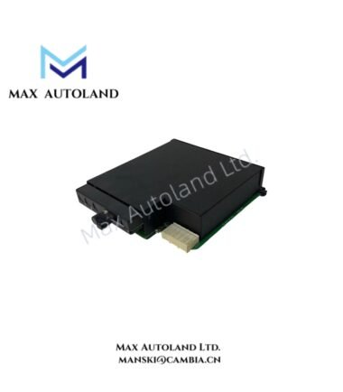
Overview
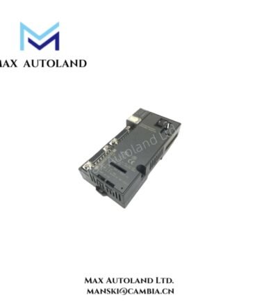
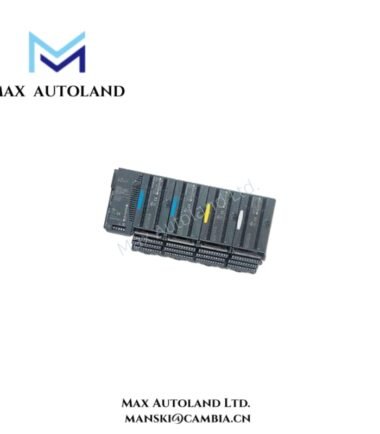
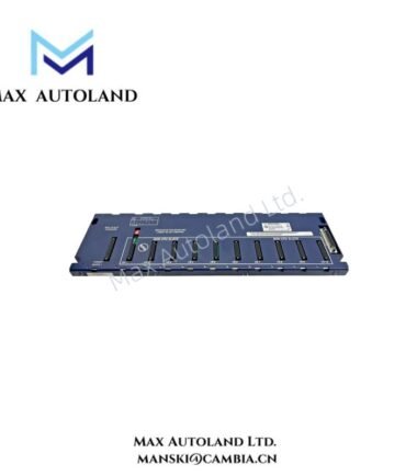
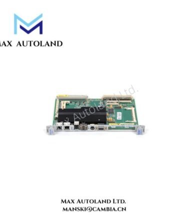
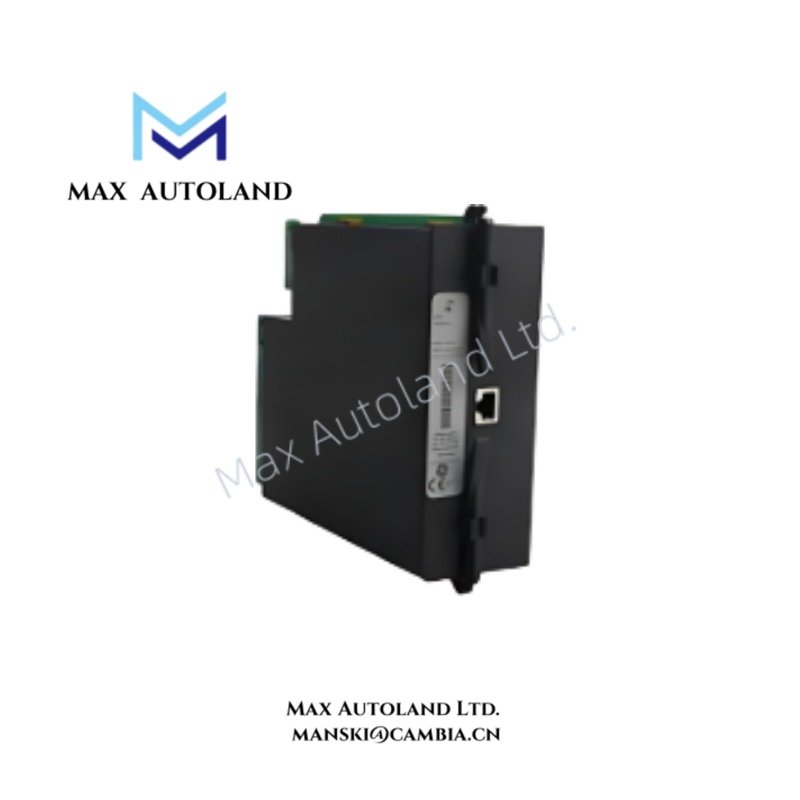
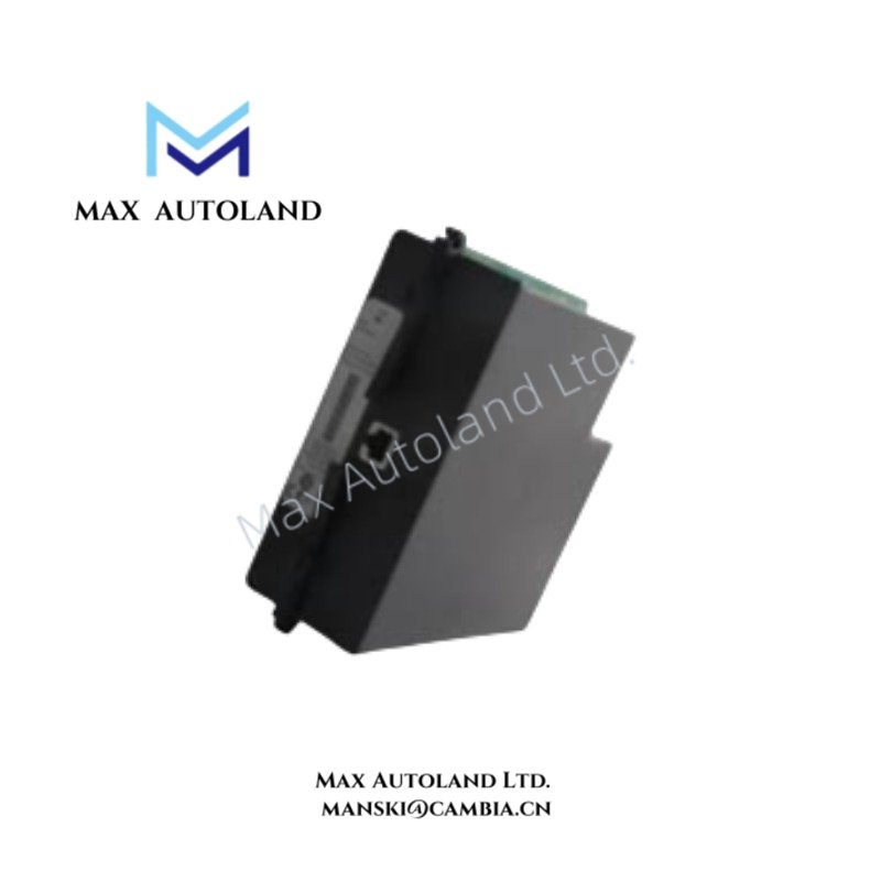
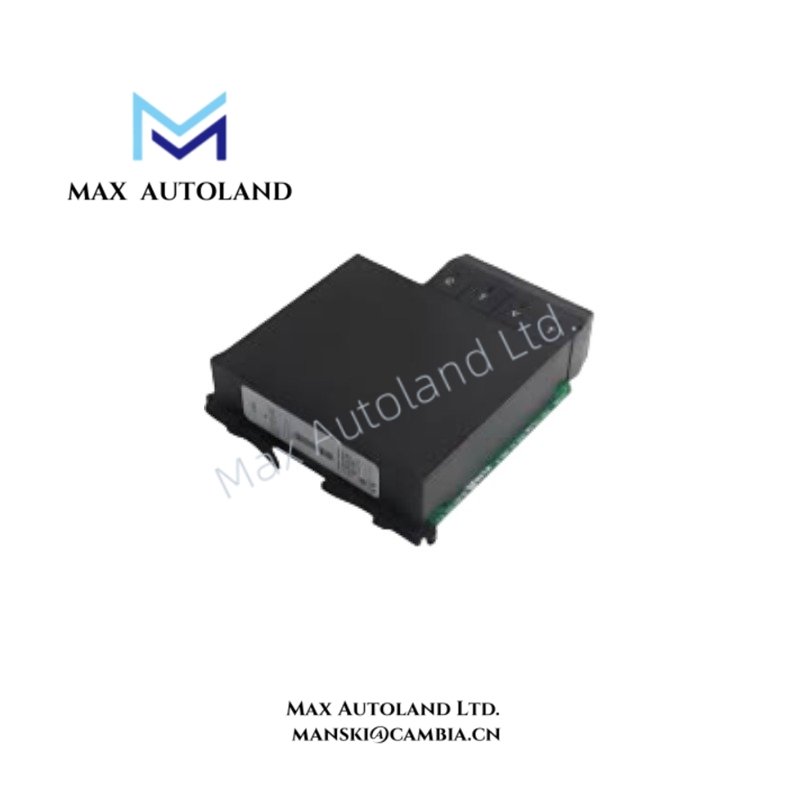
The GE UR9VM, also cataloged as the UR9VM Multilin Universal Relay Module, operates as a dedicated hardware component for signal processing, monitoring, and data exchange within GE Multilin Universal Relay Series platforms.
Hardware Specifications
| Parameter | Specification |
|---|---|
| Model | UR9VM |
| Brand | General Electric (GE Multilin) |
| Product Type | Universal Relay Module |
| Series | GE Multilin UR Series |
| Origin | USA |
| Weight | Approx. 1 kg |
| Dimensions | Approx. 250 x 190 x 50 mm |
| Operating Temp | -40 deg C to +60 deg C |
| Storage Temp | -40 deg C to +85 deg C |
| Relative Humidity | Up to 95% non-condensing |
| Power Consumption | Supplied through UR chassis power module |
| Mounting Type | Rack / chassis mounted |
| Platform Compatibility | GE Multilin Universal Relay chassis |
| Configuration | Modular plug-in hardware design |
| Communication Support | UR Series communication architecture |
| Application | Protection, monitoring, metering, and automation systems |
Industrial Control Bus and Firmware Compatibility
The GE UR9VM module is designed for integration within the GE Multilin UR modular hardware architecture. The module operates through the UR chassis backplane communication structure and exchanges processed data with CPU, power supply, communication, and I/O modules.
The UR platform supports configurable protection and control architectures through modular I/O density scaling. System firmware compatibility depends on the installed UR relay configuration and supported hardware revision. The module is configured through the GE UR engineering environment for application-specific functions.
Frequently Asked Questions
Q: Can the UR9VM module operate independently outside a GE Multilin UR chassis?
A: No. The UR9VM is a chassis-based module and requires installation in a compatible GE Multilin Universal Relay platform for operation.
Q: Does the UR9VM include an independent power supply circuit?
A: No. The module receives operating power from the UR chassis power supply module through the internal hardware connection.
Q: What installation condition should be verified before module replacement?
A: The replacement module hardware compatibility, firmware support, and relay configuration parameters should be checked before installation.
Field Installation Guidelines
- Verify the UR chassis model and available slot configuration before installation.
- Disconnect the chassis power source before inserting or removing the module.
- Align the module with the designated rack guide and ensure full mechanical engagement.
- Maintain proper grounding and shielding practices for connected communication wiring.
- Avoid routing communication cables parallel to high-voltage power conductors.
- Confirm firmware compatibility and perform functional verification after module installation.
- Review relay configuration parameters before returning the protection system to service.