


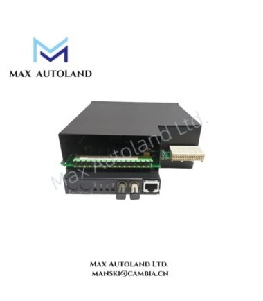

Overview
Configured for current and voltage acquisition in UR-series protection relays, the GE UR8RH (UR8RH CT/VT Module) provides direct analog signal interfacing to the Universal Relay backplane for sampled measurement processing within UR platform architectures. The GE UR8RH operates as a dedicated hardware component for transformer-scaled electrical signal acquisition in modular relay systems.
Hardware Specifications
| Parameter | Specification |
|---|---|
| ModelBrand | GE UR8RH |
| Origin | USA |
| Weight | 0.22 kg |
| Dimensions | 38 mm × 115 mm × 45 mm |
| OperatingTemp | N/A |
| PowerConsumption | N/A |
| Function | CT/VT analog measurement interface module for UR relay backplane |
| Interface | UR series internal backplane connector |
| Signal Type | Scaled current and voltage inputs via external CT/VT circuits |
Backplane Bus Communication and Firmware Compatibility
The UR8RH integrates into the GE Multilin UR backplane architecture where deterministic internal data exchange governs sampled value transport between measurement modules and relay CPU processing units. The module behavior is dependent on backplane synchronization timing and firmware revision alignment within the UR platform. Firmware flash compatibility is maintained at system level, requiring matched UR controller and module revision sets to ensure consistent CT/VT scaling interpretation and channel mapping integrity.
Frequently Asked Questions
Q: Does the UR8RH support hot-swap insertion under energized system conditions?
A: The module is not designed for live insertion in energized relay backplane configurations. System de-energization is required prior to module replacement to prevent backplane signal disturbance.
Q: What is the electrical impact of the UR8RH on backplane loading?
A: The module contributes to internal backplane communication loading only. External burden is determined by connected CT/VT circuits rather than the module itself.
Q: Is firmware alignment required between UR8RH and UR CPU modules?
A: Yes. UR platform operation requires compatible firmware versions to ensure correct scaling, channel mapping, and sampled value interpretation.
Field Installation Guidelines
The UR8RH shall be installed into the designated UR chassis slot with full mechanical seating into the backplane connector. All CT secondary circuits must remain shorted or burdened according to standard transformer safety practice prior to energization. VT inputs shall be fused according to system design to prevent overvoltage propagation into the measurement interface. Shielding conductors should be terminated at a single-point ground reference to minimize induced measurement noise. Module insertion shall be performed only after complete system power isolation.