Overview
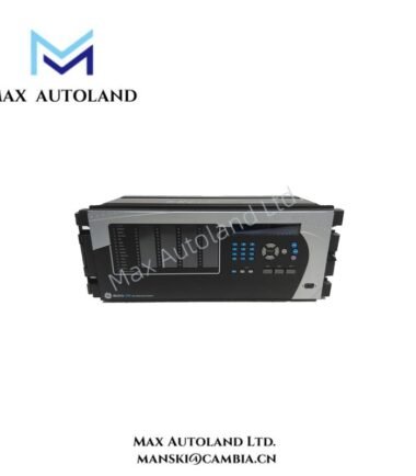
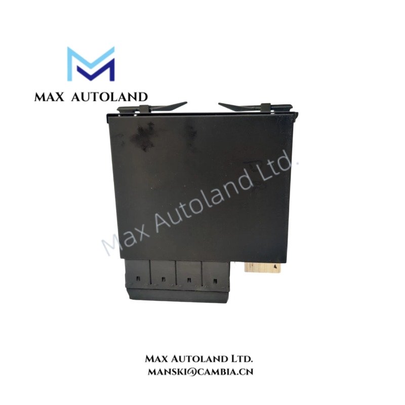
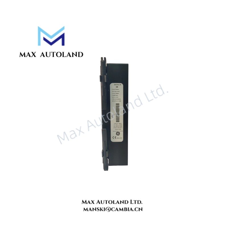
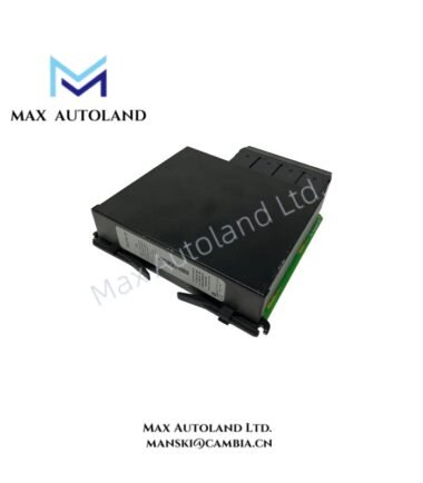
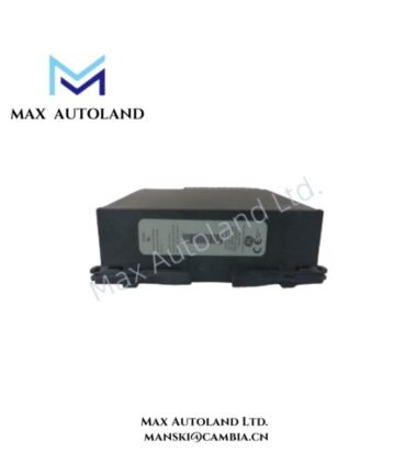
Configured for digital signal acquisition and relay command execution in the GE Multilin Universal Relay system, the GE Multilin UR6BH (UR6BH Digital I/O Module) provides direct physical and electrical interface control for external protection circuits.
Hardware Specifications
| Parameter | Specification |
|---|---|
| Model | UR6BH (UR-6BH) |
| Brand | GE Multilin |
| Origin | General Electric, USA |
| Module Type | Digital Input / Output Module |
| Application Platform | GE Multilin Universal Relay (UR) Series |
| Compatible Systems | T60, G60, L90, F60, B30 and other UR chassis platforms |
| Dimensions | Standard UR-series plug-in module format |
| Operating Temp | -40 deg C to +60 deg C |
| Storage Temp | -40 deg C to +85 deg C |
| Power Consumption | Supplied through UR chassis backplane; exact consumption depends on configuration |
| Digital Input Voltage | 24 VDC, 48 VDC, 110 VDC, 125 VDC, 220 VDC, 250 VDC configurable options |
| Input Threshold | Typically 70% to 80% of nominal input voltage |
| Electrical Isolation | Galvanic isolation between field circuits and relay electronics |
| Output Contact Type | Form-A normally open or Form-C changeover contacts depending on configuration |
| Output Rating | Up to 30 A for 0.2 s trip duty; continuous carry rating depends on contact configuration |
| Input Response Time | Typically within milliseconds for status detection |
| Output Response Time | Typically less than 8 ms for standard relay outputs |
| Communication Interface | Internal UR high-speed module bus connection |
| Event Recording | Sequence of Events (SOE) time-stamped input monitoring support |
GE Industrial Relay Backplane and I/O Architecture
The UR6BH operates as a modular interface card within the GE Multilin UR platform. It exchanges digital status and control data through the relay internal backplane communication structure. Therefore, the module allows protection logic processors to receive external contact changes and issue control outputs without external signal conversion equipment.
The UR platform supports firmware flash compatibility across supported relay configurations. In addition, the modular architecture enables I/O density scaling by adding compatible field interface modules according to application requirements.
The module design includes electrical separation between field wiring and internal processing circuits. Furthermore, input filtering and isolation functions reduce the influence of transient disturbances commonly present in substation control circuits.
Frequently Asked Questions
Q: Can the GE Multilin UR6BH be installed or removed while the relay remains energized?
A: The UR platform supports modular replacement features; however, hot-swap operation depends on the specific UR chassis configuration and manufacturer installation procedures.
Q: Does the UR6BH communicate directly with external SCADA networks?
A: No. The UR6BH provides local digital field interface functions. SCADA communication is handled through the main UR relay communication modules and processors.
Q: What field wiring practices are recommended for the UR6BH module?
A: Field wiring should maintain separation between control circuits and high-energy conductors. Shielding, grounding, and terminal protection should follow the site electrical installation standards.
Field Installation Guidelines
- Install the UR6BH module into the designated UR-series chassis slot according to the relay hardware configuration guide.
- Verify the module position and terminal assignment before connecting field wiring.
- Use appropriate shielded cables for control circuits operating in electrically noisy environments.
- Connect cable shields according to site grounding practice to minimize electromagnetic interference.
- Separate digital input wiring from high-voltage power cables and high-current switching circuits.
- Confirm input voltage ratings before applying external DC control signals.
- Check relay configuration software settings after installation to ensure correct digital input and output mapping.
- Perform functional testing of breaker status, trip, close, and alarm circuits before placing the protection system into service.