
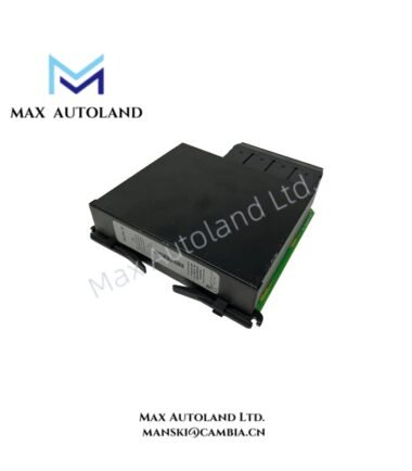
Overview
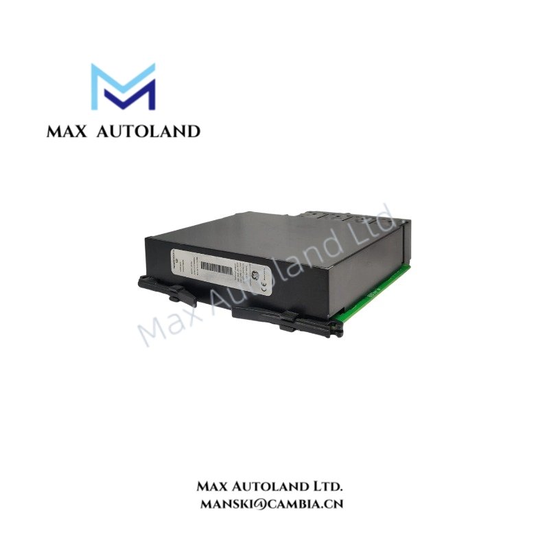
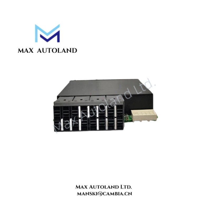
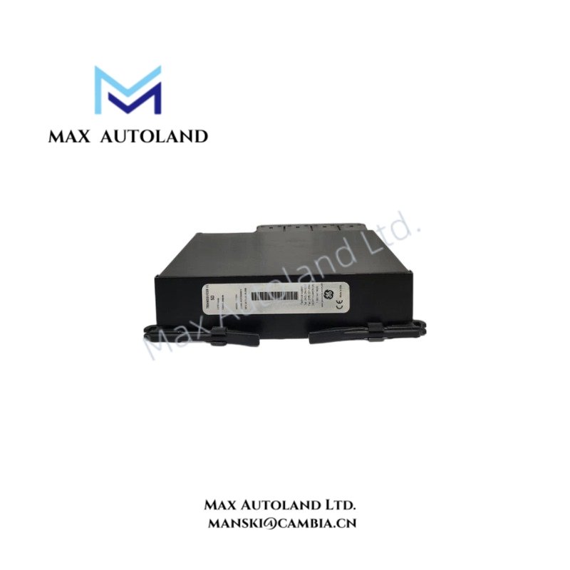
The GE Multilin UR5DH, also cataloged as the UR5DH Universal Relay hardware module, operates as a dedicated protection and control component for signal processing, I/O execution, and communication tasks within GE Multilin UR Series relay platforms.
Hardware Specifications
| Parameter | Specification |
|---|---|
| Model | GE Multilin UR5DH |
| Brand | GE Multilin |
| Origin | Canada |
| Weight | Not specified in available documentation |
| Dimensions | 4U rack-mount UR chassis compatible module configuration |
| Operating Temp | -40 deg C to +60 deg C |
| Power Consumption | Up to 45 W depending on installed hardware configuration |
| System Platform | GE Multilin Universal Relay (UR) Series |
| Application Type | Protection, control, metering, and substation automation |
| Power Input Range | 24 – 48 VDC or 110 – 250 VDC typical UR power supply options |
| AC Input Range | 120 – 240 VAC, 50/60 Hz depending on power supply module |
| Current Input Rating | 1 A or 5 A CT secondary inputs depending on installed CT/VT module |
| Voltage Input Rating | Up to 300 VAC phase-to-neutral depending on installed analog module |
| Digital Input Type | Optically isolated contact inputs |
| Communication Ports | Ethernet, RS232, RS485 interfaces depending on installed communication module |
| Communication Protocols | IEC 61850, Modbus RTU/TCP, DNP 3.0, IEC 60870-5-104 |
| Mounting Method | 19-inch rack mounting system |
| Firmware Type | Flash programmable UR platform firmware |
Backplane Bus Communication and Flash Compatibility
The GE Multilin UR5DH uses the modular UR hardware architecture, where the installed CPU, power supply, communication, and I/O modules exchange data through the internal backplane bus. Therefore, the module configuration determines available protection functions, measurement channels, and communication resources.
The UR platform supports firmware flash compatibility, which allows configuration updates through the EnerVista software environment when the installed hardware revision meets firmware requirements. In addition, programmable FlexLogic functions execute internal control equations for protection and automation sequences.
The UR5DH configuration supports deterministic data exchange between relay hardware modules. However, the exact available functions depend on the complete ordering code, including the protection relay model and installed option modules.
Profinet / EtherNet/IP Deterministic Networks and I/O Density Scaling
The UR5DH operates within a modular GE Multilin relay system that supports industrial communication expansion through dedicated Ethernet and serial communication modules. The communication architecture enables integration with IEC 61850 substation networks, Modbus systems, and DNP-based control environments.
The modular I/O structure allows I/O density scaling by adding digital input, digital output, CT/VT measurement, and communication modules. Furthermore, the relay maintains synchronized protection data exchange between measurement channels and processing units.
Frequently Asked Questions
Q: Does the GE Multilin UR5DH operate as a standalone protection relay?
A: No. The UR5DH identifies a hardware configuration within the GE Multilin UR platform. The complete relay function depends on the installed CPU, power supply, protection firmware, and I/O modules.
Q: Can the UR5DH hardware configuration support firmware upgrades?
A: Yes. The GE Multilin UR platform uses flash programmable firmware. The installed hardware revision must match the supported firmware compatibility requirements.
Q: Does the UR5DH support hot-swap replacement of modules?
A: Module replacement procedures depend on the specific UR chassis configuration and installed module type. Maintenance personnel must follow GE Multilin service procedures and isolate power before removing hardware modules.
Field Installation Guidelines
- Install the UR5DH configuration inside the specified GE Multilin UR chassis with correct module slot assignment.
- Verify the chassis backplane connection before applying auxiliary power.
- Use shielded cables for analog measurement circuits and terminate shields according to site grounding practices.
- Separate CT, VT, digital control, and communication wiring to reduce electromagnetic interference.
- Confirm terminal polarity for current transformer and voltage transformer circuits before energizing the relay.
- Check communication addressing, protocol settings, and network parameters before connecting the relay to the substation control network.
- Perform insulation, wiring continuity, and functional verification tests after installation.
- Apply firmware updates only with compatible UR hardware revisions and approved configuration files.


