
Overview
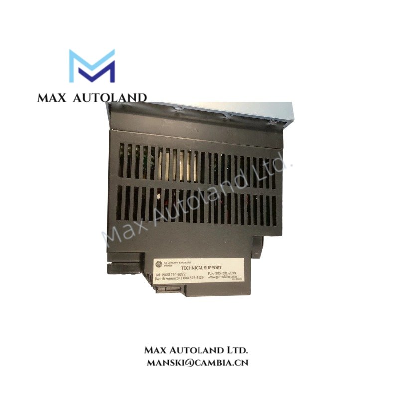
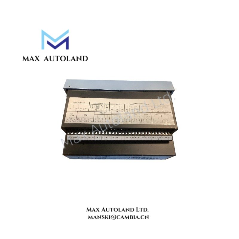
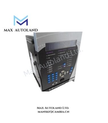
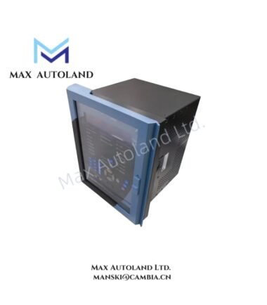
Configured for harmonic distortion monitoring and power parameter acquisition in industrial electrical networks, the GE PQMII-C-A (PQMII-C Power Quality Meter) provides direct physical measurement execution. This unit interfaces via rear RS485 ports and front RS232 communication channels to deliver real-time electrical data without macro-level system descriptions.
Hardware Specifications
| Parameter | Specification |
|---|---|
| Model Brand | General Electric (GE) |
| Origin | USA |
| Weight | 5.74 kg |
| Dimensions | 11 cm x 6 cm x 12 cm |
| Operating Temp | 0 degC to 50 degC (Standard Industrial) |
| Power Consumption | 20 VA |
| Control Power | 20-60 VDC / 20-48 VAC or 90-300 VDC / 70-265 VAC |
| Frequency | 50/60 Hz |
| Analog Input | One (1) 4-20 mA |
| Analog Outputs | Four (4) Isolated Analog Outputs |
| Digital I/O | Four (4) Output Relays / Four (4) Switch Inputs |
| Communication | Modbus, 2 Rear RS485 Ports, 1 Front RS232 Port |
| Display | Digital Display with LED Indication |
Backplane Bus Communication Velocity Licenses
The PQMII-C-A utilizes deterministic backplane bus protocols to ensure data integrity across distributed control systems. Firmware flash compatibility is maintained through licensed GE software packages, ensuring that configuration downloads do not corrupt setpoint logic during power cycling. Channel response scaling is fixed to prevent latency in alarm relay actuation.
Frequently Asked Questions
Q: Does the PQMII-C-A support hot-swap functionality on the RS485 network?
A: No. Power must be isolated before removing or installing the unit to prevent backplane bus voltage spikes and communication errors.
Q: What is the maximum burden for the analog output loops?
A: Each isolated 4-20 mA output supports a maximum loop resistance of 600 ohms at 24 VDC supply levels.
Q: Are the switch inputs dry contacts or wet?
A: The four switch inputs are dry contact types requiring external excitation for state detection.
Field Installation Guidelines
Mount the device using the provided screw terminals into a standard panel cutout. Ensure the rear RS485 ports are shielded with twisted pair cabling, and ground the shield drain wire at one end only to prevent ground loops. Torque terminal screws to 0.5 Nm. Verify control power polarity before applying voltage to avoid damaging the internal power supply module.