
Overview
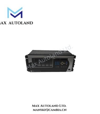
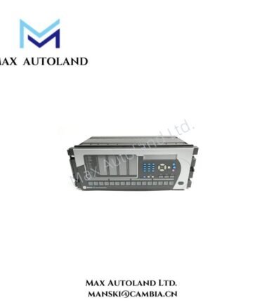
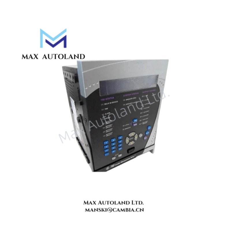
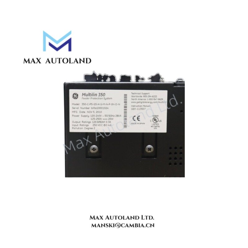
Configured for overcurrent discrimination and lockout execution in medium voltage distribution networks, the GE 350-C-P5-G5-H-S-M-N-P-SN-D-N (Multilin 350 Feeder Protection System) provides direct physical trip circuit actuation and rear bus communication via RS485.
Suffix Breakdown & Model Matrix
| Code Segment | Parameter | Description |
|---|---|---|
| 350 | Base Series | Multilin 350 Feeder Protection System |
| C | Configuration | Standard Configuration |
| P5 | Phase Current Input | 5 A Three-Phase Current Inputs |
| G5 | Ground Current Input | 5 A Ground Current Input |
| H | Power Supply | 125–250 VDC or 100–240 VAC |
| S | Front Panel Interface | Standard Front Panel Interface with Keypad and Display |
| M | Communications | Front USB, Rear RS485 (Modbus RTU / DNP3.0 support) |
| N | Control Selection | No Control Selections |
| P | Additional Functions | Standard Phase, Neutral, Ground, and Voltage Metering Functions |
| SN | I/O Configuration | Standard I/O (10 Contact Inputs, 7 Outputs) |
| D | Case Design | Drawout Case Design |
| N | Harsh Environment | No Conformal Coating (Standard Environment) |
Hardware Specifications
| Parameter | Specification |
|---|---|
| Model Brand | GE Multilin |
| Origin | Canada |
| Weight | Approx. 3.2 kg |
| Dimensions | 177.8 mm x 177.8 mm x 229 mm |
| Operating Temp | -40 degC to +60 degC |
| Power Consumption | < 15 W typical |
| Phase Current Input | 5 A nominal, 3-phase |
| Ground Current Input | 5 A nominal |
| Digital Inputs | 10 opto-isolated, selectable threshold |
| Relay Outputs | 7 total (2 Form A, 5 Form C) |
| Communication Ports | Front USB, Rear RS485 |
Backplane Bus Communication Velocity Licencing
The rear RS485 interface operates under deterministic timing constraints compliant with Modbus RTU and DNP 3.0 protocol stacks. Message latency remains below 10 ms under full I/O scan loads when interfaced to compatible GE Multilin host controllers. Firmware flash compatibility is restricted to 350 series hardware revisions issued after 2015; cross-flashing older base firmware results in checksum rejection at power-up.
Frequently Asked Questions
Q: Does the drawout case support hot-swap replacement without interrupting rear terminal wiring?
A: Yes. The drawout mechanism allows withdrawal of the relay core while maintaining all external conductors on the fixed termination module. Trip circuits must be manually bypassed before removal.
Q: Are the 10 contact inputs electrically isolated from the internal logic supply?
A: All digital inputs employ opto-isolation referenced to independent return terminals. Isolation withstand rating is 2.5 kV RMS for 1 minute per IEC 60255-5.
Q: Can the device operate with only DC supply voltage applied?
A: Yes. The H-range power supply accepts 125–250 VDC without AC presence. AC and DC supply ranges are mutually exclusive and internally diode-ORed for redundancy.
Field Installation Guidelines
Mount the relay into a vertical panel cutout sized to 178 mm x 178 mm. Secure the drawout chassis using four M6 bolts torqued to 4.0 Nm. Terminate all shielded control cables with the shield drain wire bonded directly to the panel ground bar within 50 mm of entry. Maintain a minimum separation of 150 mm between AC power conductors and current transformer secondary wiring to prevent magnetic coupling. Verify current transformer polarity before closing the breaker feed to avoid false directional tripping.