


Overview
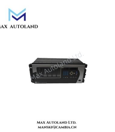
Configured for feeder overcurrent protection and circuit breaker control in electrical distribution networks, the GE Multilin MIFIIPI11E1RHI00 (MIF II Feeder Protection Relay) provides direct physical and electrical execution for phase and ground current monitoring, trip logic, and autoreclosing functions.
Hardware Specifications
| Parameter | Specification |
|---|---|
| Model | MIFIIPI11E1RHI00 |
| Brand | GE Multilin |
| Product Series | MIF II Feeder Protection Relay |
| Origin | GE Grid Solutions |
| Protection Function | Phase/Ground Overcurrent, Instantaneous Overcurrent, Thermal Overload, Breaker Failure, Autoreclosing |
| Current Input | 5 A nominal phase and ground current input |
| Frequency Range | 50/60 Hz +/- 3 Hz |
| Protection Pickup Range | 0.10 to 2.40 x In for TOC, 0.1 to 30.0 x In for IOC |
| Operating Time | Less than 30 ms for instantaneous overcurrent operation |
| Autorecloser | 1 to 4 configurable shots |
| Digital Outputs | 6 programmable output relays |
| Communication Ports | Front RS-232 and rear RS-485 |
| Communication Protocols | Modbus RTU, IEC 60870-5-103 |
| Display Interface | 2 x 16 character backlit LCD with 5-button keypad |
| Event Recorder | Stores up to 32 events |
| Waveform Recording | Analog and digital oscillography support |
| Auxiliary Power Supply | 110 to 250 V DC / 110 to 230 V AC +/- 20% |
| Operating Temp | -20 deg C to +60 deg C |
| Power Consumption | Less than 10 W nominal |
Industrial Control and Communication Features
The GE Multilin MIF II relay integrates digital signal processing with feeder protection logic for distribution system applications. It measures phase and ground currents through 5 A CT inputs and executes programmed protection functions based on configured pickup values and time curves.
The relay supports IEC and ANSI protection characteristics, including Standard Inverse, Very Inverse, Extremely Inverse, IEEE curves, and user-defined curves. In addition, the device applies thermal overload calculation through a configurable heating time constant from 3 to 600 minutes.
Furthermore, the MIF II platform supports GE EnerVista M II setup software for relay configuration, event analysis, and maintenance operations. The RS-485 communication interface enables integration with supervisory systems through Modbus RTU or IEC 60870-5-103 protocols.
The relay also provides industrial control compatibility through configurable logic outputs, breaker control functions, and autoreclose sequencing. Moreover, the device supports Profinet / EtherNet-IP deterministic networks only through external communication gateways because the standard MIFIIPI11E1RHI00 configuration uses serial communication interfaces.
Frequently Asked Questions
Q: Does the MIFIIPI11E1RHI00 support hot-swappable replacement during operation?
A: No. The MIF II relay uses a fixed panel-mounted construction and requires controlled isolation of auxiliary power and field wiring before replacement.
Q: What communication protocols are available on the relay hardware?
A: The relay provides Modbus RTU and IEC 60870-5-103 communication through the rear RS-485 port, while the front RS-232 port supports local communication.
Q: How does the relay process overcurrent protection signals?
A: The relay samples phase and ground current inputs, applies configured pickup thresholds and time curves, then activates programmable output relays for trip and control operations.
Field Installation Guidelines
- Install the relay in a protected panel environment with suitable mechanical support and grounding provisions.
- Connect current transformer secondary wiring according to the specified 5 A input configuration and maintain correct polarity.
- Use shielded communication cables for RS-232 and RS-485 connections where electromagnetic interference may affect signal quality.
- Ground cable shields according to site grounding standards and avoid routing communication wiring parallel to high-current power conductors.
- Verify auxiliary supply voltage before energizing the relay. The MIFIIPI11E1RHI00 high-voltage supply option accepts 110 to 250 V DC or 110 to 230 V AC.
- Configure protection settings through GE EnerVista M II software before placing the relay into service.
- Perform functional tests for trip outputs, breaker control logic, autoreclose sequences, and communication links after installation.