
Overview
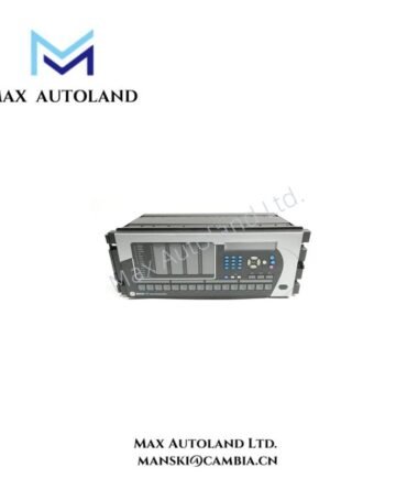
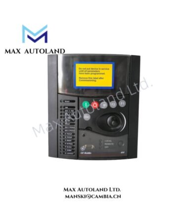
Configured for feeder protection, measurement, and bay control execution in electrical distribution systems, the GE Multilin F650-B-F-C-F1-G0-HI-6H (F650 Digital Feeder Protection Relay) provides direct monitoring and control of current, voltage, frequency, and circuit breaker functions.
Hardware Specifications
| Parameter | Specification |
|---|---|
| Model | F650-B-F-C-F1-G0-HI-6H |
| Brand | GE Multilin |
| Product Type | Digital Feeder Protection Relays |
| Origin | Canada |
| Weight | Not specified in available technical data |
| Dimensions | 1/2 x 19 inch rack, 4U draw-out enclosure |
| Operating Temp | -40 deg C to +70 deg C |
| Power Consumption | Approximately 30 W / 30 VA |
| Auxiliary Power Supply | 110 – 250 VDC or 120 – 230 VAC, 50/60 Hz |
| Phase Current Inputs | 1 A / 5 A AC configurable CT inputs |
| Ground Current Inputs | 1 A / 5 A AC standard ground CT input |
| Voltage Inputs | Configurable 100 – 240 VAC phase-to-phase VT inputs |
| Frequency Range | 50/60 Hz nominal |
| Display Interface | Graphical LCD with programmable single-line diagram, LEDs, and control pushbuttons |
| Communication Ports | Ethernet and RS485 serial communication interfaces |
| Ethernet Protocols | IEC 61850 Edition 1/2, Modbus TCP/IP, DNP3.0 |
| Serial Protocols | Modbus RTU, DNP3 |
| Time Synchronization | IRIG-B, IEEE 1588 PTP, SNTP |
| Protection Functions | Overcurrent, earth fault, voltage, frequency, thermal, breaker failure, auto-reclose |
| Front Panel Protection | IP54 |
Industrial Control and Communication Features
The GE Multilin F650 series integrates feeder protection functions with bay control operations through configurable logic, measurement processing, and communication interfaces. Therefore, the relay processes electrical input signals and transfers protection status, measurements, and control commands through Ethernet and serial networks.
The unit supports deterministic substation communication through IEC 61850 and provides compatibility with Modbus TCP/IP and DNP3 protocols. In addition, the Ethernet interface allows integration with supervisory control systems while the RS485 port supports serial field communication.
The F650 platform applies industrial control architecture features, including backplane communication management, firmware compatibility control, and scalable I/O configuration. Furthermore, the relay supports programmable logic functions for breaker control, interlocking, and feeder automation sequences.
Protection and Bay Control Functions
The F650-B-F-C-F1-G0-HI-6H executes the following protection and control functions:
- Phase overcurrent protection: 50P, 51P
- Ground overcurrent protection: 50G, 51G
- Directional overcurrent protection: 67P, 67N, 67G
- Undervoltage protection: 27
- Overvoltage protection: 59
- Neutral overvoltage protection: 59N
- Underfrequency protection: 81U
- Overfrequency protection: 81O
- Rate of change of frequency protection: df/dt
- Thermal overload protection: 49
- Auto-reclose function: 79 with synchronism check 25
- Breaker failure protection: 50BF
- Trip circuit supervision: 74TC
- Cold load pickup function
- Load encroachment function
Frequently Asked Questions
Q: Does the F650-B-F-C-F1-G0-HI-6H support IEC 61850 communication?
A: Yes. The relay provides Ethernet communication with IEC 61850 Edition 1 and Edition 2 support for substation automation networks.
Q: What type of current transformers can connect to the F650 relay?
A: The relay accepts configurable phase and ground CT inputs rated for 1 A or 5 A AC nominal current signals.
Q: Can the relay perform breaker control functions locally?
A: Yes. The graphical LCD interface, programmable logic, pushbuttons, and LEDs support local breaker control, status indication, and interlocking functions.
Field Installation Guidelines
- Install the F650 relay inside a compatible 19 inch rack panel using the specified draw-out mounting arrangement.
- Connect CT secondary wiring according to the configured 1 A or 5 A input selection and verify polarity before energization.
- Route current transformer, voltage transformer, communication, and control wiring separately to reduce electromagnetic interference.
- Apply shield grounding practices according to the substation grounding design and maintain proper cable termination.
- Verify Ethernet addressing, protocol configuration, and time synchronization settings before connecting the relay to the control network.
- Confirm trip circuit supervision wiring and breaker control outputs before placing the feeder protection system into service.