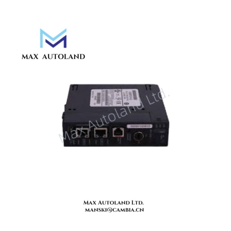
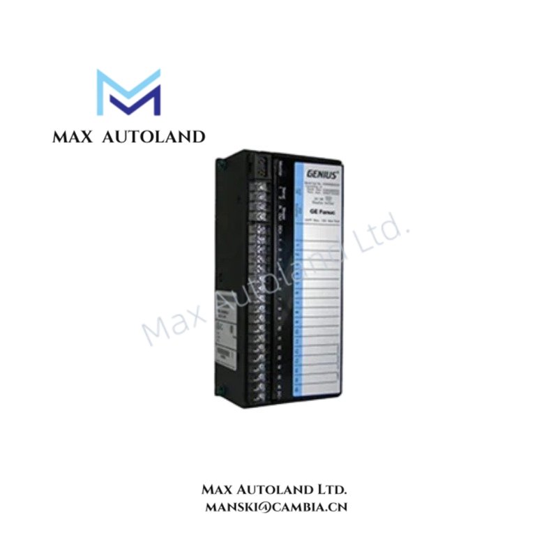
Overview
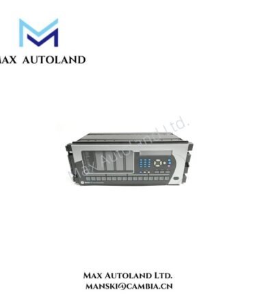
Configured for feeder protection, control, and monitoring tasks in electrical substation networks, the GE F35E00VFHF8FH6TM6TPXX (F35 Feeder Protection System) provides direct physical/electrical execution.
Suffix Breakdown & Model Matrix
- F35: Base Model (Feeder Protection System)
- E: CPU Module (Advanced CPU with high-performance processing and standard IEC 61850 capabilities)
- 00: No Software Options (Standard configuration)
- V: Power Supply Option (88-300 VDC / 85-264 VAC)
- FH: Faceplate / User Interface (Standard front panel with display, navigation keys, and LED status indicators)
- F8F / H6T / M6T: I/O and Communication Modules (Specific combinations of Current Transformer (CT) / Voltage Transformer (VT) inputs, digital inputs, and form-A/B relay outputs)
- PXX: Communication protocol and port configurations (Standard Ethernet/serial ports supporting Modbus, DNP3, and IEC 61850)
Hardware Specifications
| Parameter | Specification |
|---|---|
| Model | F35E00VFHF8FH6TM6TPXX |
| Brand | GE Multilin |
| Origin | United States |
| Weight | Standard UR Series housing weight |
| Dimensions | Standard UR Series 19-inch rack unit enclosure |
| OperatingTemp | -40 degC to +60 degC (-40 degF to 140 degF) |
| PowerConsumption | Standard UR series power limits |
| Power Supply (V Option) | 88-300 VDC / 85-264 VAC |
| CT/VT Inputs | 1 A / 5 A dual-rated current inputs; standard voltage inputs |
| Frequency Support | 50 Hz and 60 Hz systems |
| Communications | RJ45 Ethernet and/or Fiber Optic ports; RS485 Serial |
| Protocols | IEC 61850, DNP 3.0, Modbus RTU/TCP, IEC 60870-5-104 |
| Enclosure Protection | IP40 (Front Panel), IP20 (Rear Terminals) |
| Configuration Software | EnerVista UR Setup Software |
Backplane Bus Communication and Firmware Flash Compatibility
The unit operates within the GE Universal Relay architecture, utilizing a high-speed internal backplane bus to ensure deterministic data transfer between the CPU module and the modular I/O cards. Firmware flash compatibility protocols govern all module-to-module data pathways, forcing automated version verification during system initialization to prevent logic execution errors during active substation protection tasks.
Frequently Asked Questions
Q: What occurs during a firmware mismatch between the CPU and the integrated I/O modules?
A: The base CPU executes a boot-time validation check. If firmware flash compatibility is violated, the system logs a self-test fault and halts execution to avoid unpredictable relay behavior.
Q: Can the I/O modules be hot-swapped while the power supply is active?
A: No. The internal backplane bus requires total de-energization before removing or inserting any modular hardware components to prevent electrical arcing and logic corruption.
Field Installation Guidelines
Ensure standard 19-inch rack mounting stability before finalizing terminal connections. All CT/VT wiring must utilize dedicated shorting blocks to avoid open-circuit conditions during maintenance. Connect the main ground bus directly to the designated copper ground terminal on the rear chassis using standard gauge wire to mitigate electromagnetic interference. Maintain minimum clearance distances around the enclosure to optimize passive thermal heat dissipation.