Overview
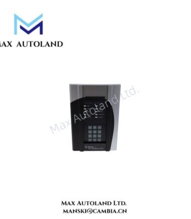
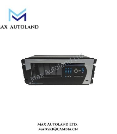
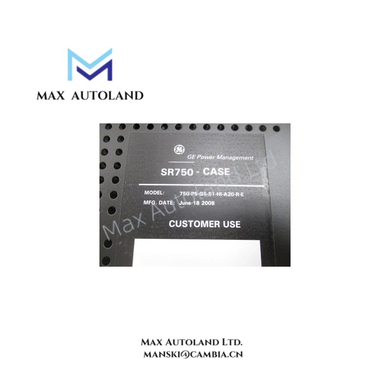
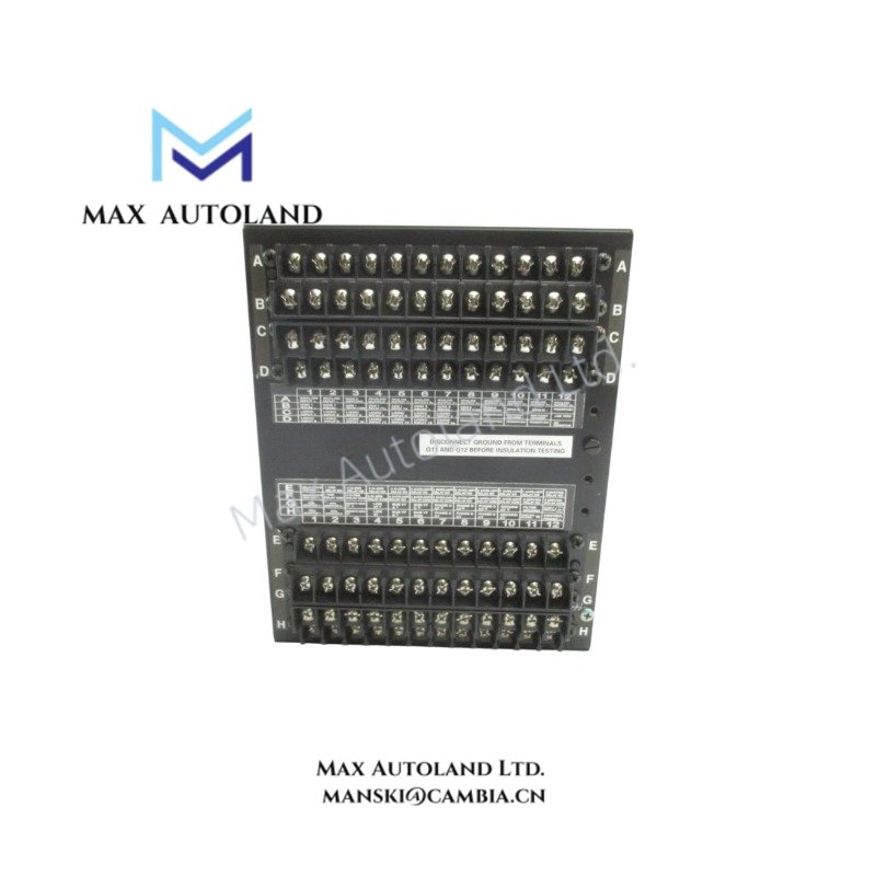
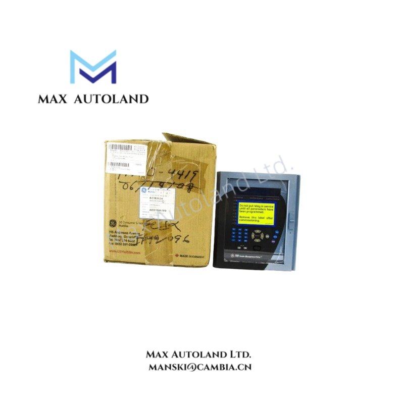
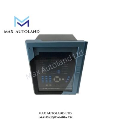
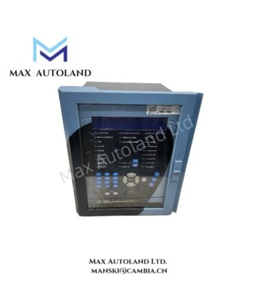
Configured for transformer differential protection and current/voltage supervision in power system protection architectures, the GE 745-W2-WP5-G5-HI (745 transformer protection relay) provides direct electrical measurement processing and trip output execution for two-winding transformer protection schemes within GE Multilin relay platforms.
Suffix Breakdown & Model Matrix
- 745: Base transformer protection relay platform
- W2: Hardware revision / enclosure configuration
- WP5: Input/output and communication configuration variant
- G5: Functional application package level
- HI: High input control power supply range option (AC/DC wide range supply support)
Hardware Specifications
| Parameter | Specification |
|---|---|
| ModelBrand | GE Multilin 745-W2-WP5-G5-HI |
| Origin | United States |
| Weight | Not specified by manufacturer |
| Dimensions | Not specified by manufacturer |
| OperatingTemp | Industrial relay standard range (manufacturer-defined, not specified in provided data) |
| PowerConsumption | Approx. 30–40 VA (control power dependent) |
| CT Secondary Input | 1 A / 5 A configurable |
| VT Input Range | 60–120 V phase-to-neutral |
| Frequency | 50 / 60 Hz |
| Measurement Range | 0.02 to 46 × CT rating |
| Overcurrent Withstand | Up to 80 × rated current for 1 s |
GE Multilin Industrial Control Architecture Signal Processing Layer
The GE 745 platform executes deterministic protection logic using embedded firmware routines synchronized with sampled current and voltage inputs. Within GE industrial control architectures, relay-to-system integration is typically executed via backplane communication interfaces and serial/Ethernet communication stacks supporting substation automation data exchange. Deterministic event handling aligns with industrial network timing constraints similar to Profinet and EtherNet/IP class architectures, where protection trips are prioritized over non-critical telemetry traffic. Firmware image execution is segmented to support controlled flash updates with rollback protection logic in protection-critical configurations.
Frequently Asked Questions
Q: Does the 745 relay support hot-swappable hardware replacement?
A: The relay does not support live hot-swap of internal protection modules. Control power must be isolated before insertion or removal to maintain CT/VT safety integrity.
Q: What is the CT burden impact on external measurement circuits?
A: CT input burden is specified as < 0.2 VA per phase, minimizing loading on external current transformer secondary circuits under normal operating conditions.
Q: Is firmware upgrade compatible with existing configuration files?
A: Firmware upgrades are generally backward-compatible within the 745 platform family; configuration retention depends on revision compatibility and must be validated during commissioning.
Field Installation Guidelines
- Maintain CT secondary shorting provisions during installation to prevent open-circuit voltage conditions
- Ensure shielded twisted pair wiring for analog CT/VT inputs with single-point grounding at panel earth
- Avoid parallel routing of relay input wiring with high-voltage switching conductors to reduce induced noise coupling
- Verify control power supply polarity and range compliance prior to energization
- Use dedicated protective grounding conductor bonded directly to relay chassis earth terminal