



Overview
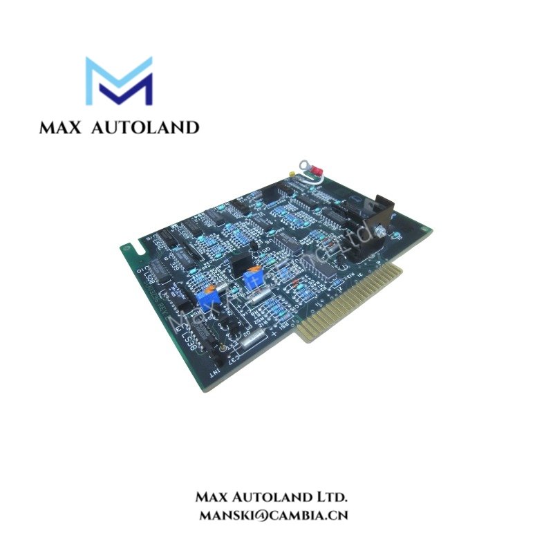
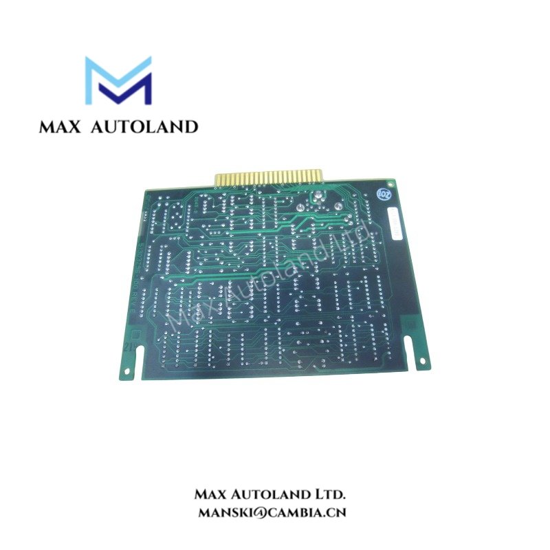
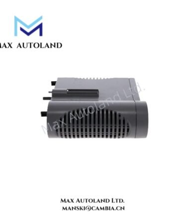
The Honeywell 51303294-100, also cataloged as the 51303294-100 Printed Circuit Board, operates as a dedicated hardware component for internal control execution and signal processing within legacy Honeywell TDC2000 automation platforms.
Suffix Breakdown & Model Matrix
| Suffix / Identifier | Functional Classification | Operational Specification |
|---|---|---|
| 51303294-100 | Base Industrial PC Board | Standard revision for legacy Honeywell process control cabinets |
Hardware Specifications
| Parameter | Specification |
|---|---|
| Model | 51303294-100 |
| Brand | Honeywell |
| Origin | USA |
| Weight | 0.9 kg |
| Dimensions | 89 × 64 × 13 mm |
| Operating Temp | 0 deg C to 60 deg C (Standard industrial rack environment) |
| Power Consumption | Dependent on backplane bus load (Nominal 5 VDC / 24 VDC rail) |
4-20 mA Loop Protocol and Signal Routing
The printed circuit board interfaces directly with process instrumentation by managing internal signal distribution across legacy control loops. It maintains standard 4-20 mA HART loop protocol parameters to ensure precise transmitter integration. Furthermore, channel-to-channel isolation prevents ground loops and voltage surges from propagating into adjacent rack slots.
Frequently Asked Questions
Q: Does this circuit board support online hot-swapping within the equipment rack?
A: No, power must be completely isolated from the specific chassis slot before extracting or inserting the circuit board to prevent bus driver corruption.
Q: What precautions are necessary for cold junction compensation (CJC) when handling thermocouple inputs through this system?
A: Technicians must ensure that terminal block ambient temperatures remain stable and that shielded compensation extension cables are properly grounded at the designated cabinet bar.
Field Installation Guidelines
- Verify that the rack power supply is completely de-energized before mounting the circuit board.
- Align the printed circuit board carefully along the internal chassis card guides to prevent backplane pin bending.
- Secure the top and bottom mounting screws firmly to maintain chassis grounding continuity and mechanical stability.









Reviews
There are no reviews yet.