
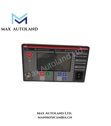
Overview
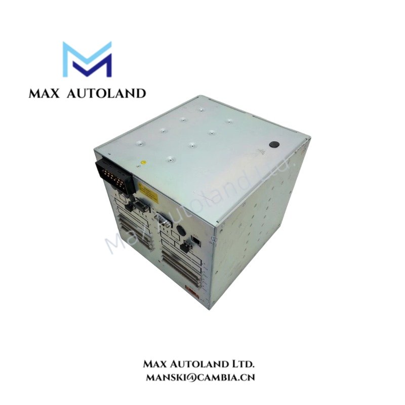
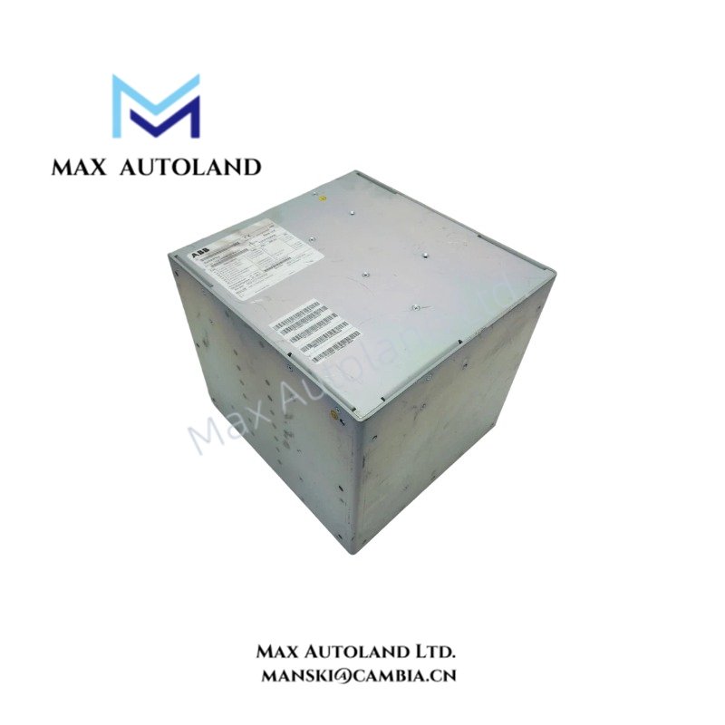
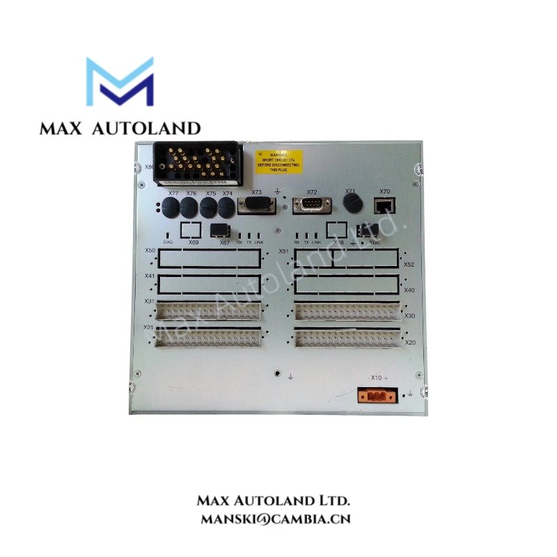
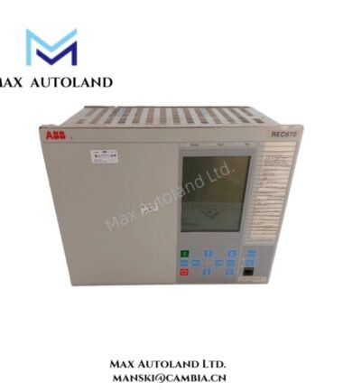
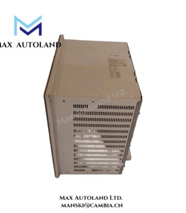
The ABB REF542plus 1VCF752000, also identified as the REF542plus feeder terminal panel, processes electrical measurements and executes protection, switching control, and monitoring functions in medium-voltage switchgear. The unit combines protection logic, measurement processing, programmable control, and communication interfaces within a configurable hardware platform.
Hardware Specifications
| Parameter | Specification |
|---|---|
| Model | REF542plus |
| Spare Model | 1VCF752000 |
| Brand | ABB |
| Product Type | Feeder Terminal Panel |
| Application | Feeder protection and switchgear control |
| System Integration | Medium-voltage switchgear automation |
| Protection Functions | Overcurrent, earth fault, voltage, frequency, and other configuration-dependent functions |
| Measurement Inputs | Conventional CT/VT inputs or compatible sensor interfaces, depending on configuration |
| Measured Quantities | Current, voltage, power, power factor, and frequency |
| Digital I/O | Configuration-dependent; source data specifies up to 42 binary inputs |
| Communication | Protocol and interface availability depend on hardware and configuration |
| Fault Recording | Configuration-dependent; supplied data specifies up to 8 analog channels and 32 binary signals |
| HMI | LCD display and navigation controls, depending on configuration |
| Self-Diagnostics | Built-in hardware and software monitoring |
| Weight | 6.66 kg |
| Dimensions | 24.5 x 28 x 18.5 cm (estimated shipping dimensions) |
Protection Logic and Switchgear Control
The REF542plus processes current and voltage measurements to support protection decisions and switchgear operating sequences. Available functions depend on the installed hardware, firmware, and application configuration.
Supported functions may include:
- Overcurrent and earth-fault protection.
- Undervoltage and overvoltage protection.
- Thermal overload and motor-start supervision.
- Frequency protection and synchronism checking.
- Automatic reclosing and directional power protection.
- Programmable interlocking and switching logic.
- Circuit-breaker condition monitoring and trip-circuit supervision.
The configured protection functions determine which measurements, binary signals, timers, and output actions participate in each protection sequence.
Communication and Hardware Compatibility
The REF542plus integrates measurement processing, protection logic, and switchgear control. Its communication interfaces exchange measurement values, status information, alarms, and control commands with compatible supervisory systems.
The supplied reference information lists IEC 61850, Modbus RTU/TCP, IEC 60870-5-103, SPA, and ABB LON as possible communication options. Confirm the installed interface hardware, firmware revision, and protocol support before integrating the unit into an existing network.
For replacement work, verify the base unit, HMI arrangement, I/O configuration, auxiliary supply, measurement input ratings, terminal assignments, and communication interfaces. The order code 1VCF752000 should be checked against the equipment nameplate and the original configuration documentation.
Frequently Asked Questions (FAQ)
Q: Can the REF542plus replace another feeder protection terminal directly?
A: Not without configuration verification. Compare the auxiliary supply, CT/VT input ratings, binary I/O assignments, trip outputs, communication interfaces, firmware, and protection settings before replacement.
Q: Which communication protocol does the REF542plus support?
A: The supplied information lists IEC 61850, Modbus RTU/TCP, IEC 60870-5-103, SPA, and ABB LON as possible options. Actual availability depends on the installed hardware and configuration.
Q: Are all protection functions available on every REF542plus unit?
A: No. The available functions depend on the application configuration, installed hardware, and firmware. Verify the device configuration and engineering documentation before commissioning.
Field Installation Guidelines
- Verify identification: Check the REF542plus model and 1VCF752000 order code against the equipment nameplate and project documentation.
- Inspect the hardware: Examine the housing, connectors, terminal blocks, and any separate HMI components for mechanical damage.
- Confirm electrical ratings: Verify the auxiliary supply, CT/VT secondary ratings, input polarity, and output contact ratings against the applicable wiring diagrams.
- Check instrument transformer circuits: Confirm CT polarity and phase allocation. Never leave an energized current transformer secondary open-circuit.
- Separate signal wiring: Route measurement, binary control, communication, and auxiliary power wiring according to the manufacturer’s installation instructions and the switchgear design.
- Apply grounding and shielding practices: Connect protective earth and cable shields according to the equipment documentation and the site’s electromagnetic compatibility requirements.
- Verify communication settings: Check protocol selection, network parameters, device addressing, and supervisory-system mappings before enabling control commands.
- Test protection and control: Validate measurement scaling, binary input states, trip logic, interlocking, alarms, and communication signals using approved commissioning procedures.
- Document the configuration: Record firmware identification, protection settings, I/O mapping, and communication parameters before returning the equipment to service.
ABB Top Products
Customers Also Viewed
Contact: Manski Wong +86 18030205725 manski@cambia.cn




Reviews
There are no reviews yet.