Overview
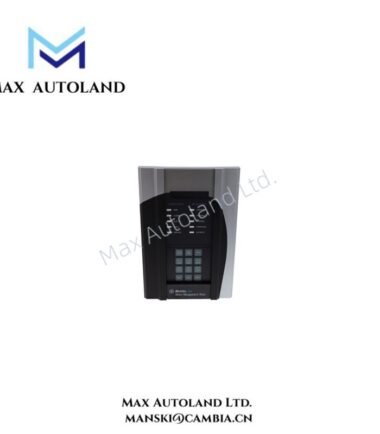
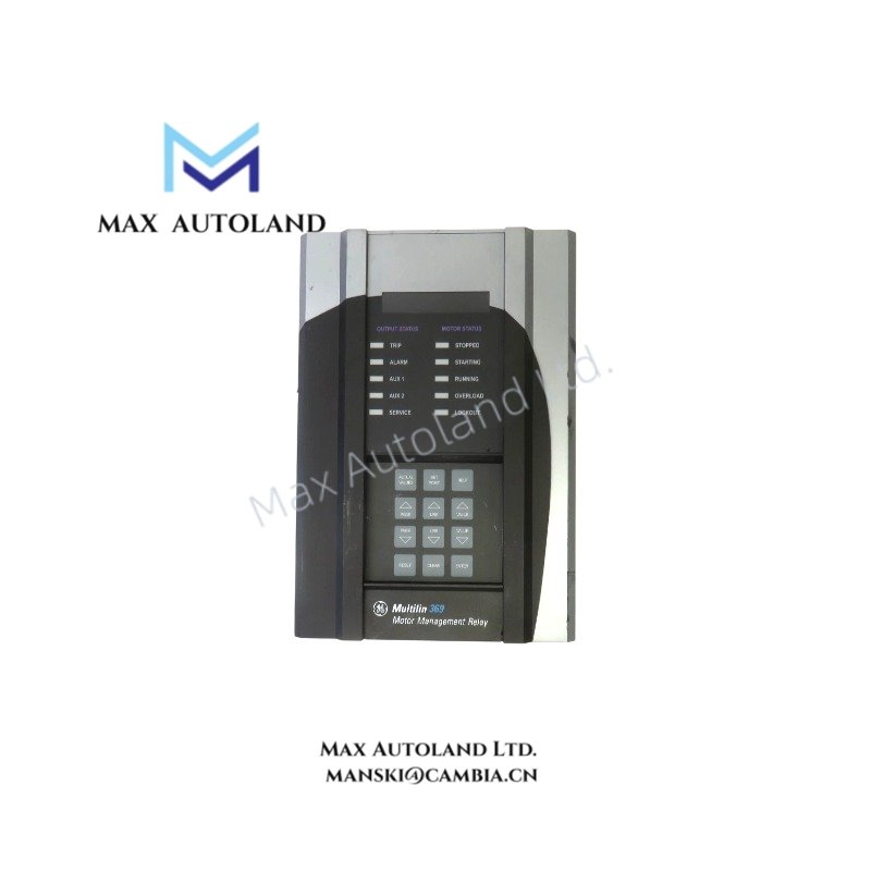
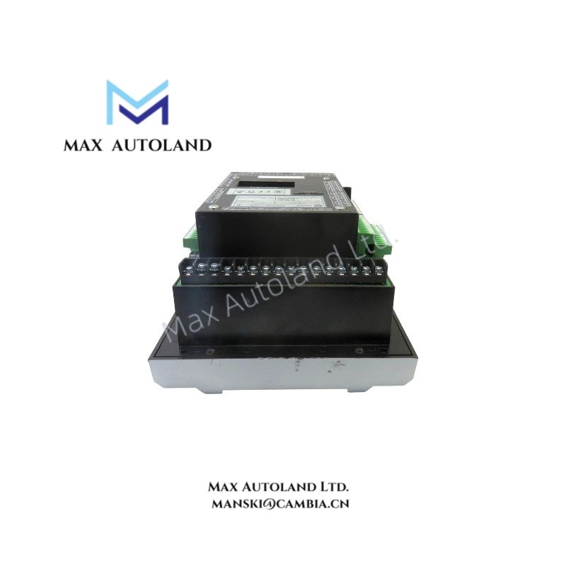
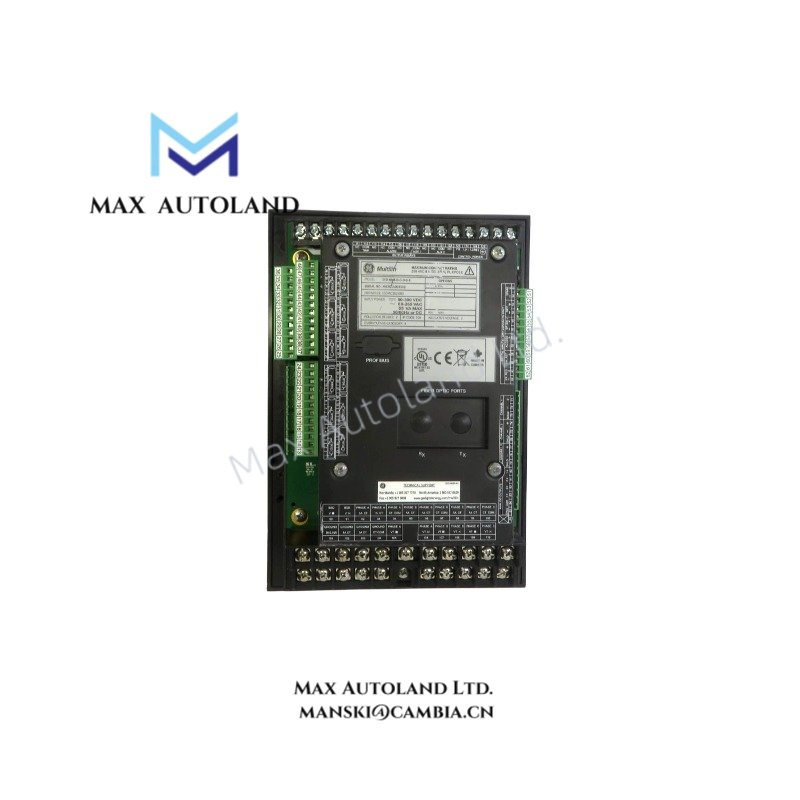
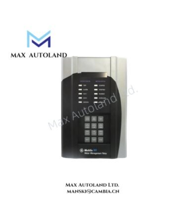
Configured for motor protection, monitoring, and control in industrial motor control systems, the GE Multilin 369-HI-R-0-0-0-0-E (369 Motor Management Relay) provides direct electrical execution. The unit supervises phase current, ground current, thermal conditions through RTD inputs, and motor operating status while supplying relay-based protection and diagnostic functions.
Suffix Breakdown & Model Matrix
The supplied documentation identifies 369-HI-R-0-0-0-0-E as a fixed catalog configuration. No official suffix decomposition beyond the documented configuration is provided.
| Parameter | Specification |
|---|---|
| Model | 369-HI-R-0-0-0-0-E |
| Brand | GE Multilin |
| Product Family | 369 Motor Management Relay |
| Product Type | Motor Management Relay |
| Manufacturer | General Electric |
| Country of Origin | USA |
| Shipping Location | Xiamen, China |
| Dimensions | 20.6 x 14 x 29.4 cm |
| Weight | 3.6 kg |
| Operating Temp | -40 deg F to +140 deg F |
| Control Power | 50-300 VDC or 60-265 VAC, 50-60 Hz |
| Phase Current Input | 1 A and 5 A secondary |
| Ground Current Input Frequency | 20 to 100 Hz |
| RTD Inputs | 12 inputs; 3-wire, 100 Ohm platinum, 100 Ohm nickel, 120 Ohm nickel, 10 Ohm copper |
| Fuse | 3.15 A H, 250 V, 5 x 20 mm |
| Diagnostics | Enhanced diagnostics |
| Faceplate | Enhanced faceplate with motor status indicators |
| Data Functions | Motor Health Report, Enhanced Learned Data, Motor Start Data Logger, Enhanced Event Recorder, Security Audit Trail |
| Power Consumption | Not specified by manufacturer documentation |
Firmware Flash Compatibility
The relay belongs to the GE Multilin 369 platform and should operate with firmware revisions approved for the corresponding hardware revision. Firmware updates should be performed only with manufacturer-supported procedures and compatible configuration software. Configuration files should be archived before maintenance to preserve protection settings, event records, and learned motor data.
Frequently Asked Questions
Q: Does this model support multiple RTD sensor types?
A: Yes. The relay supports 12 RTD inputs and accepts 3-wire 100 Ohm platinum, 100 Ohm nickel, 120 Ohm nickel, and 10 Ohm copper RTDs.
Q: Can the relay operate from either AC or DC control power?
A: Yes. The specified control power range is 50-300 VDC or 60-265 VAC at 50-60 Hz.
Q: Is hot replacement supported while the relay remains energized?
A: The provided documentation does not specify hot-swap capability. Removal or replacement should follow the equipment manufacturer’s maintenance procedure with control power isolated unless the installation documentation explicitly permits energized servicing.
Field Installation Guidelines
- Verify that the available control power matches the specified AC or DC input range before energizing the relay.
- Connect phase current transformers according to the selected 1 A or 5 A secondary configuration and maintain correct polarity.
- Route RTD wiring separately from power conductors to reduce electrical noise.
- Terminate cable shields using the site’s grounding practice to minimize induced interference.
- Install the specified 3.15 A H 250 V fuse before commissioning.
- Confirm CT ratios, RTD assignments, protection settings, and event recording parameters before placing the relay into service.