
Overview
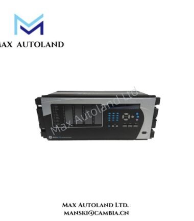
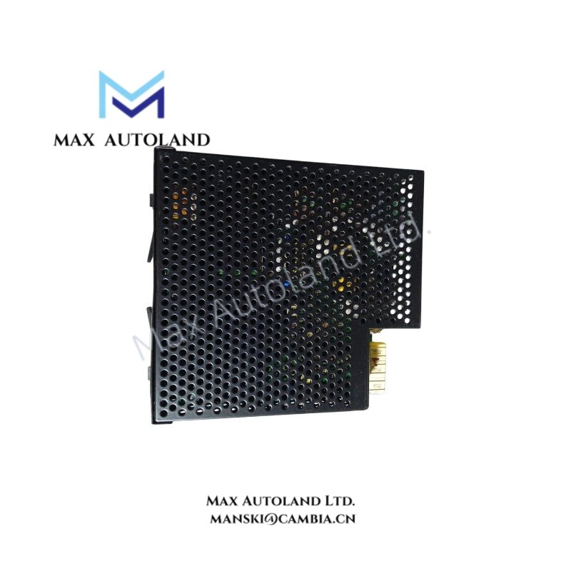
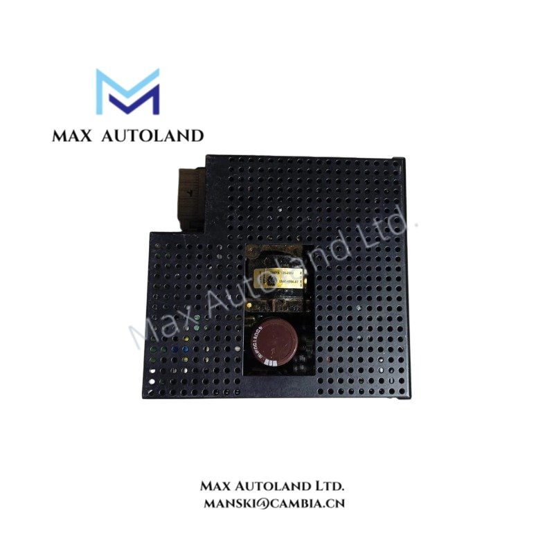
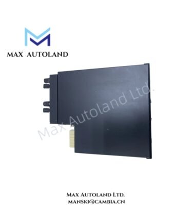
Configured for DC power conversion and backplane distribution in UR-series protection racks, the GE Multilin URSHB (UR-SHB Power Supply Module) provides direct physical/electrical execution within Universal Relay chassis architectures.
Hardware Specifications
| Parameter | Specification |
|---|---|
| ModelBrand | GE Multilin UR-SHB |
| Origin | USA |
| Weight | 0.36 kg |
| Dimensions | 8.2 cm x 12.2 cm x 6 cm |
| OperatingTemp | Not specified (refer to UR rack environmental rating) |
| PowerConsumption | Not specified |
| Input Voltage | 88 to 250 V AC/DC nominal |
| Output Voltage | 48 V DC auxiliary supply |
| Product Type | Power Supply Module for UR Relay System |
GE UR Series Backplane Power Distribution Characteristics
The GE UR-SHB module interfaces with the UR relay chassis backplane to deliver regulated low-voltage DC distribution to internal relay logic and I/O subsystems. Power conversion stage supports wide-range AC/DC input tolerance for stabilized 48 V DC rail generation under fluctuating substation auxiliary supplies.
Backplane communication architecture within GE UR platforms is designed for deterministic internal data exchange, supporting synchronized module initialization and firmware compatibility alignment across plug-in cards. Firmware flash coordination across UR system modules ensures version-consistent operation during hot insertion or module replacement cycles. Internal architecture supports I/O density scaling through chassis expansion without altering power regulation topology.
Frequently Asked Questions
Q: Can the UR-SHB module be hot-swapped under energized rack conditions?
A: Hot-swap capability depends on UR chassis design; insertion must follow backplane sequencing to avoid transient DC bus disturbance.
Q: What is the supported input range stability behavior?
A: The module accepts 88 to 250 V AC/DC input and regulates downstream conversion to a fixed 48 V DC rail under internal control regulation.
Q: Does firmware mismatch affect power module operation?
A: Power module operation is independent of relay logic firmware but must maintain chassis compatibility for backplane synchronization integrity.
Field Installation Guidelines
Install the module only in designated UR-series chassis slots with verified backplane alignment. Ensure system power is fully isolated before insertion or removal. Maintain correct seating force to secure edge connector engagement without lateral stress.
Shielding and grounding continuity must be maintained through rack chassis earth points. Avoid partial insertion states during energized conditions to prevent transient voltage reflection on the DC bus. Verify auxiliary input wiring conforms to rated insulation class for 250 V AC/DC environments.
Do not bend or stress the backplane connector during installation or maintenance operations.