
Overview
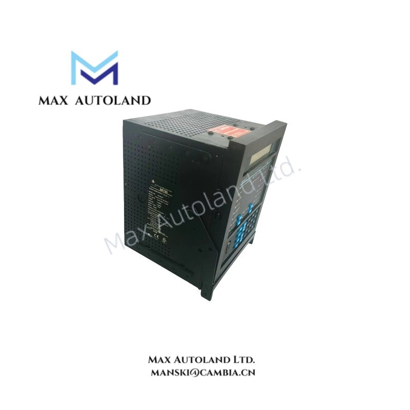
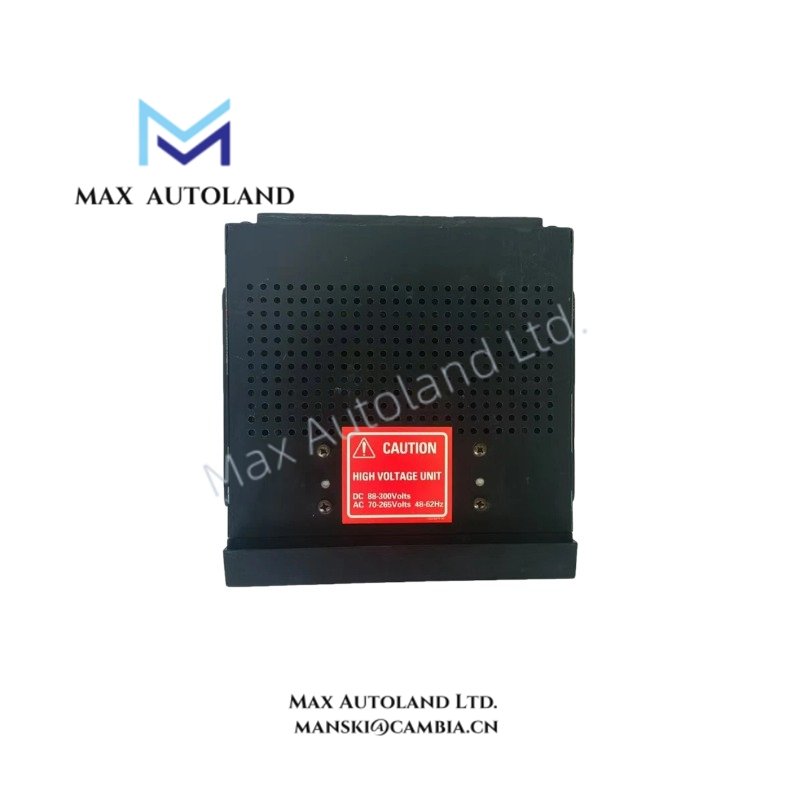
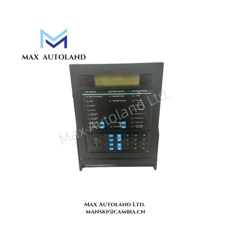
Configured for feeder overcurrent discrimination and breaker trip execution in medium-voltage distribution networks, the GE Multilin SR750, also cataloged as the SR750 Feeder Management Relay, provides direct physical interruption control via integrated protection algorithms and deterministic logic processing.
Hardware Specifications
| Parameter | Specification |
|---|---|
| Model Brand | GE Multilin SR750 |
| Origin | Canada |
| Weight | 2.1 kg |
| Dimensions | 177.8 mm x 177.8 mm x 203.2 mm |
| Operating Temp | -40 degF to +140 degF |
| Power Consumption | 12 W typical @ 120 VAC |
| Current Inputs | 1 A or 5 A CT secondary |
| Control Power | 70–265 VAC / 88–300 VDC (high range); 20–48 VAC / 20–60 VDC (low range option) |
| Insulation Voltage | 300 V |
| Communication Ports | RS-232, RS-485, Optional Ethernet |
| Analog Outputs | 0–1 mA, 0–5 mA, 0–10 mA, 4–20 mA (configurable) |
Backplane Bus Communication Velocity
The SR750 employs a high-speed backplane bus architecture optimized for deterministic data exchange between I/O modules and the processor core. Firmware flash compatibility is maintained across SR750 series revisions without requiring hardware replacement, ensuring consistent execution timing under high network load conditions.
Frequently Asked Questions
Q: Does the SR750 support hot-swap operation while the feeder remains energized?
A: No. Removal or insertion must occur only after de-energizing the drawout case to prevent arcing and logic disruption.
Q: What is the maximum allowable control power fluctuation before relay reset occurs?
A: The relay sustains operation within ±20% of nominal voltage; excursions beyond this range cause restart sequencing.
Q: Is firmware upgrade possible via Ethernet?
A: Yes. Firmware images can be transferred via Modbus TCP/IP using GE EnerVista software without interrupting protection logic execution.
Field Installation Guidelines
Mount the SR750 in a vertical orientation inside the cubicle to ensure convection cooling efficiency. Torque terminal screws to 0.8 Nm and maintain minimum 6 mm spacing between AC power and communication wiring to suppress inductive coupling. Connect CT secondaries before energizing primary circuits to avoid open-circuit transients. Verify insulation resistance exceeds 100 Mohm at 500 VDC prior to closing breaker contacts.