

Overview
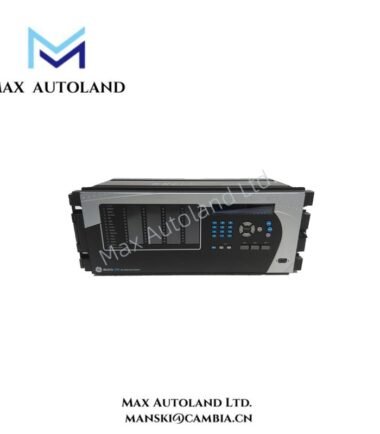
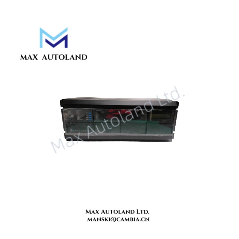
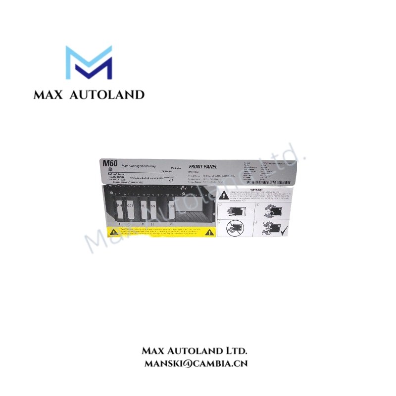
Configured for motor current, voltage, temperature, and protection logic execution in GE Universal Relay (UR) system platforms, the GE Multilin M60A00HCHF8AH6TM8AP5CU5CW5E (M60 Motor Protection Relay) provides direct physical and electrical protection functions for medium and large motor circuits.
Hardware Specifications
| Parameter | Specification |
|---|---|
| Model | GE Multilin M60A00HCHF8AH6TM8AP5CU5CW5E |
| Brand | GE Multilin |
| Product Type | Motor Protection Relay |
| Series | Universal Relay (UR) Family |
| Origin | USA |
| Dimensions | Standard UR modular rack format; exact dimensions depend on chassis configuration |
| Operating Temp | -40 deg C to +60 deg C |
| Power Consumption | Depends on installed I/O modules and configuration |
| Control Power Supply | 120 – 250 VDC / 120 – 240 VAC |
| CT Inputs | 1 A or 5 A secondary current inputs |
| VT Inputs | Configurable AC voltage inputs |
| Protection Functions | Motor thermal model, overcurrent, ground fault, voltage, frequency, and motor start protection |
| RTD Inputs | Multi-channel RTD monitoring for motor thermal measurement |
| Communication Ports | Ethernet and RS485 interfaces |
| Communication Protocols | IEC 61850, Modbus RTU/TCP, DNP 3.0, IEC 60870-5-104 |
| Mounting Type | Panel or rack mounting |
GE Multilin UR Platform Communication and Control Features
The GE Multilin M60 integrates with the Universal Relay (UR) architecture through modular hardware design and internal communication buses. The relay processes sampled electrical signals from CT and VT inputs, then executes protection algorithms through its embedded processor.
Furthermore, the M60 supports deterministic network communication through IEC 61850, Modbus TCP, DNP 3.0, and IEC 60870-5-104 interfaces. These communication functions allow the relay to exchange protection status, measurement data, event records, and control commands with substation automation systems.
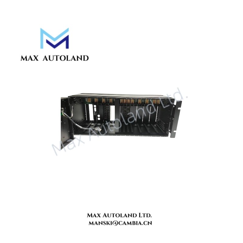
The relay supports I/O density scaling through configurable module positions. Therefore, users can install measurement, digital I/O, RTD, and communication expansion modules according to application requirements.
The firmware architecture supports configuration management, protection setting storage, and compatibility control between hardware modules and operating software revisions.
Frequently Asked Questions
Q: Does the GE Multilin M60 support hot-swapping of installed modules?
A: The M60 uses a modular UR hardware architecture. Module replacement must follow GE Multilin maintenance procedures, and power isolation is required unless the specific module type is documented as hot-swappable.
Q: What temperature inputs can the M60 RTD module monitor?
A: The RTD module supports motor temperature measurement using common RTD types such as Pt100, Cu10, and Ni120 sensors.
Q: Which communication networks can connect to the M60 relay?
A: The M60 supports IEC 61850, Modbus RTU/TCP, DNP 3.0, and IEC 60870-5-104 communication protocols through configured communication interfaces.
Field Installation Guidelines
- Install the relay inside a suitable protective panel enclosure with proper mechanical support for the UR chassis.
- Connect CT and VT circuits using shielded wiring with correct polarity and terminal identification.
- Separate low-level RTD wiring from high-current power cables to reduce electrical interference.
- Ground cable shields according to site grounding practices and protection system requirements.
- Verify control power polarity and voltage range before energizing the relay.
- Confirm communication cable routing, termination, and network addressing before system commissioning.
- Apply motor protection settings according to measured motor parameters, starting characteristics, and operating conditions.
- Check digital input and output wiring before enabling motor control functions.