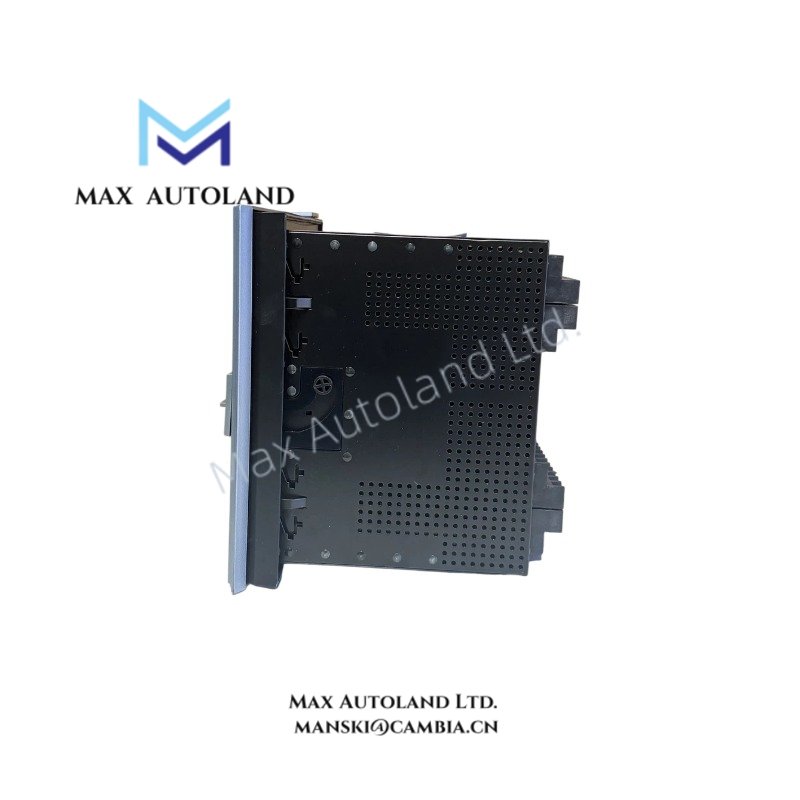
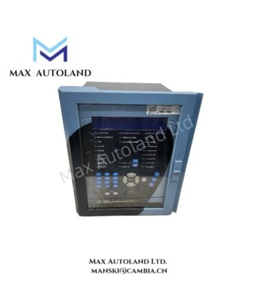
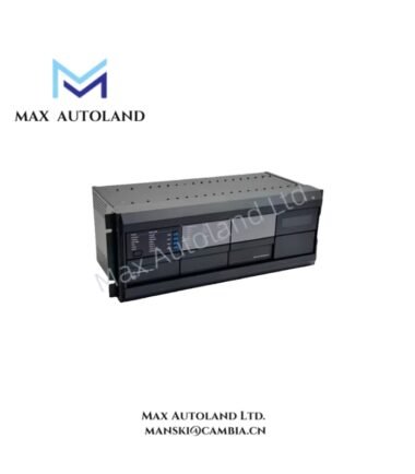
Overview
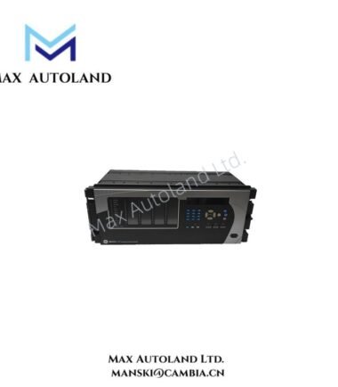
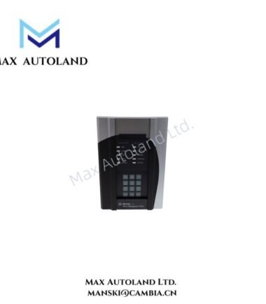
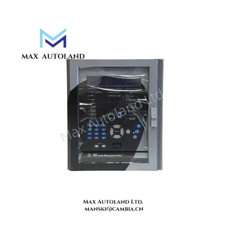
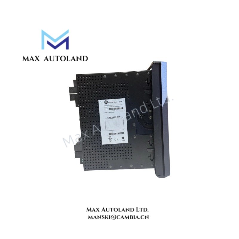
The GE Multilin SR750 750-P5-G5-S5-HI-A20-G-E, also cataloged as the SR750 Feeder Management Relay, operates as a dedicated hardware component for feeder protection, monitoring, control, and fault management within electrical distribution protection systems. The unit performs real-time electrical protection functions, event recording, status supervision, and feeder control through integrated relay logic and communication interfaces.
Suffix Breakdown & Model Matrix
The supplied documentation identifies the complete ordering code as SR750 750-P5-G5-S5-HI-A20-G-E. No official suffix decoding information is provided in the available source material; therefore, individual option code assignments are not expanded.
Hardware Specifications
| Parameter | Specification |
|---|---|
| Model | SR750 750-P5-G5-S5-HI-A20-G-E |
| Brand | GE Multilin |
| Product Family | GE Multilin 750/760 Feeder Management Relay |
| Product Type | Feeder Distribution Protection Relay |
| Manufacturer | General Electric |
| Alternate Part Number | SR 750-P5-G5-S5-HI-A20-G |
| Origin | General Electric Manufacturing Platform |
| Weight | 7.74 kg |
| Dimensions | 21.7 cm x 22.7 cm x 25 cm |
| Operating Temp | -40 degF to +140 degF |
| Storage Temp | -40 degF to +176 degF |
| Frequency | 25 to 60 Hz nominal |
| Insulation Voltage | 300 V |
| Manual Reference | 1601-0120-AE |
| Power Consumption | Not specified in supplied documentation |
PLC Communication and Firmware Compatibility Considerations
As part of the GE Multilin protection platform, the SR750 is intended for integration with substation automation and industrial control architectures where deterministic protection response is required. System deployment should verify firmware compatibility across connected relay fleets before commissioning or replacement activities.
Backplane communication parameters, protocol implementation revisions, and relay firmware versions should remain consistent with the associated protection engineering files and configuration databases. During maintenance activities, configuration backups should be archived prior to firmware updates or hardware replacement to preserve protection settings and event records.
Frequently Asked Questions
Q: Does the SR750 support hot-swapping while energized?
A: The supplied documentation does not specify hot-swap capability. Relay replacement should be performed according to site lockout/tagout procedures and applicable electrical isolation requirements.
Q: What insulation rating is specified for the relay?
A: The documented insulation voltage rating is 300 V.
Q: What environmental temperature limits apply to installation and storage?
A: The operating temperature range is -40 degF to +140 degF. The storage temperature range is -40 degF to +176 degF.
Field Installation Guidelines
- Mount the relay in accordance with enclosure and panel mechanical requirements specified by the equipment manufacturer.
- Verify all CT, VT, control power, trip circuit, and communication wiring against approved protection drawings before energization.
- Maintain segregation between low-level signal wiring and higher-energy power conductors to reduce electrical interference.
- Terminate cable shields using the facility grounding philosophy and avoid uncontrolled multiple shield grounding points.
- Confirm protective earth continuity before applying control power.
- Perform secondary injection testing, logic verification, and trip-path validation after installation or replacement.
- Archive relay settings and event records before maintenance activities involving firmware changes or hardware exchange.
- Inspect terminal torque, conductor condition, and environmental sealing during commissioning and periodic maintenance intervals.