
Overview
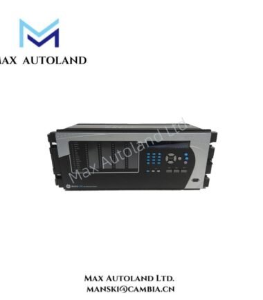
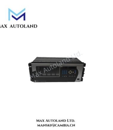
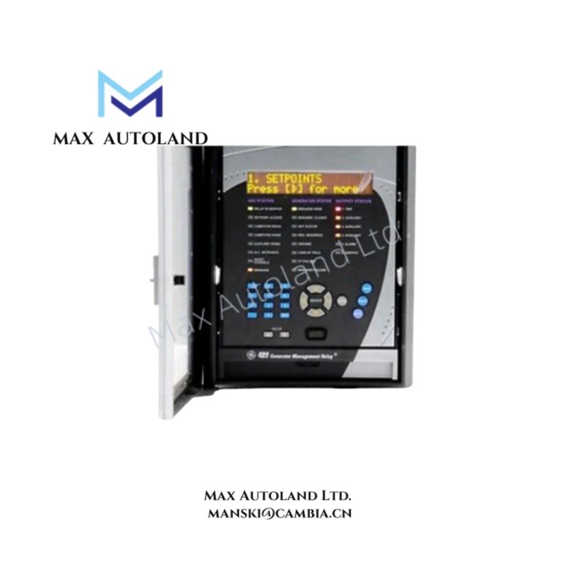
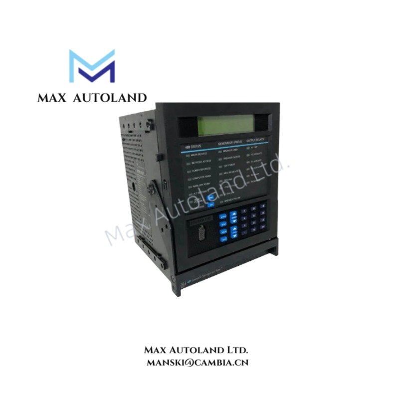
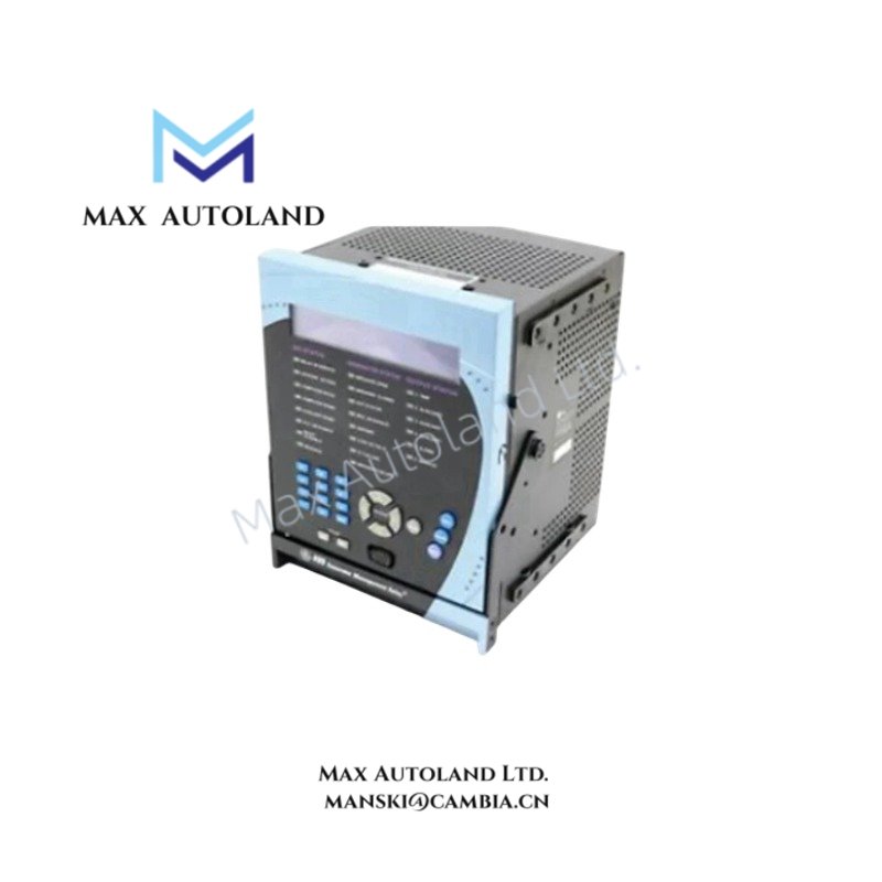
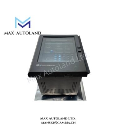
Configured for generator protection and control in industrial power systems, the GE Multilin 489-P5-HI-A20-E-H (489) generator management relay provides direct physical and electrical execution of protection schemes, monitoring stator and rotor conditions through phase CT inputs and programmable logic outputs.
Suffix Breakdown & Model Matrix
| Suffix Code | Description |
|---|---|
| SR 489 | Base Generator Management Relay Series |
| P5 | 5 A Phase CT Secondaries |
| HI | High Control Power Range (90-300 V DC / 70-265 V AC) |
| A20 | Four 4-20 mA Analog Outputs |
| E | Enhanced Display with Larger LCD |
| H | Harsh Environment Conformal Coating |
Hardware Specifications
| Parameter | Specification |
|---|---|
| Brand | GE Multilin |
| Origin | Canada |
| Dimensions | 9.0 in x 10.0 in x 10.0 in (22.9 cm x 25.4 cm x 25.4 cm) |
| Weight | 19 lbs (8.6 kg) |
| Control Power | 90 to 300 V DC; 70 to 265 V AC (48 to 62 Hz) |
| Phase Current Inputs | 5 A CT Secondaries |
| Analog Outputs | Four (4) 4-20 mA |
| Operating Temp | -40 degC to +60 degC (with harsh environment coating) |
| Mounting | Drawout Unit (Case sold separately) |
| Tariff Code | 85364900 |
Firmware Flash Compatibility & Backplane Logic
Firmware revisions must match the hardware revision level to ensure deterministic execution of protection algorithms. The relay utilizes a proprietary backplane communication protocol for high-speed data exchange with adjacent Multilin devices. Configuration files (.GCF) are not forward-compatible between major firmware versions. Field upgrades require verification of flash memory capacity against the target firmware image size.
Frequently Asked Questions
Q: Is the SR489 enclosure included with the drawout unit?
A: No. This part number (SR 489-P5-HI-A20-E-H) is the relay insert only. The SR489 case must be ordered separately.
Q: Can the 4-20 mA outputs drive inductive loads directly?
A: No. The analog outputs are sourcing/sinking current loops intended for measurement. Use external snubber circuits or isolation barriers if connecting to inductive actuators.
Q: What is the function of the harsh environment coating?
A: The “H” suffix indicates a polyurethane-based conformal coating applied to the PCB, providing resistance to chemical vapors, salt mist, and high humidity, suitable for IEC 60721-3-3 classifications.
Field Installation Guidelines
Install the drawout unit into the case using the integral guide rails. Ensure the control power is disconnected before insertion or removal. Torque the power and CT terminations to 1.2 N·m (10.6 lb-in). For harsh environments, verify the integrity of the front cover gasket seal. Ground the chassis via the dedicated ground lug using a minimum 10 AWG conductor. Route CT wiring away from AC power conductors to prevent induced noise on sensitive metering circuits.