Overview
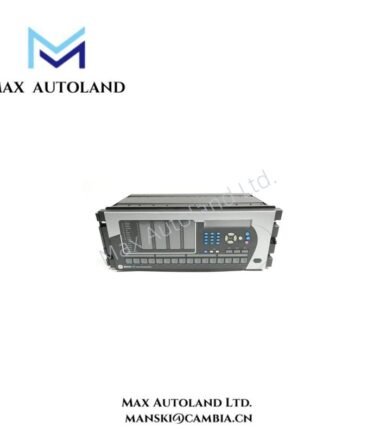
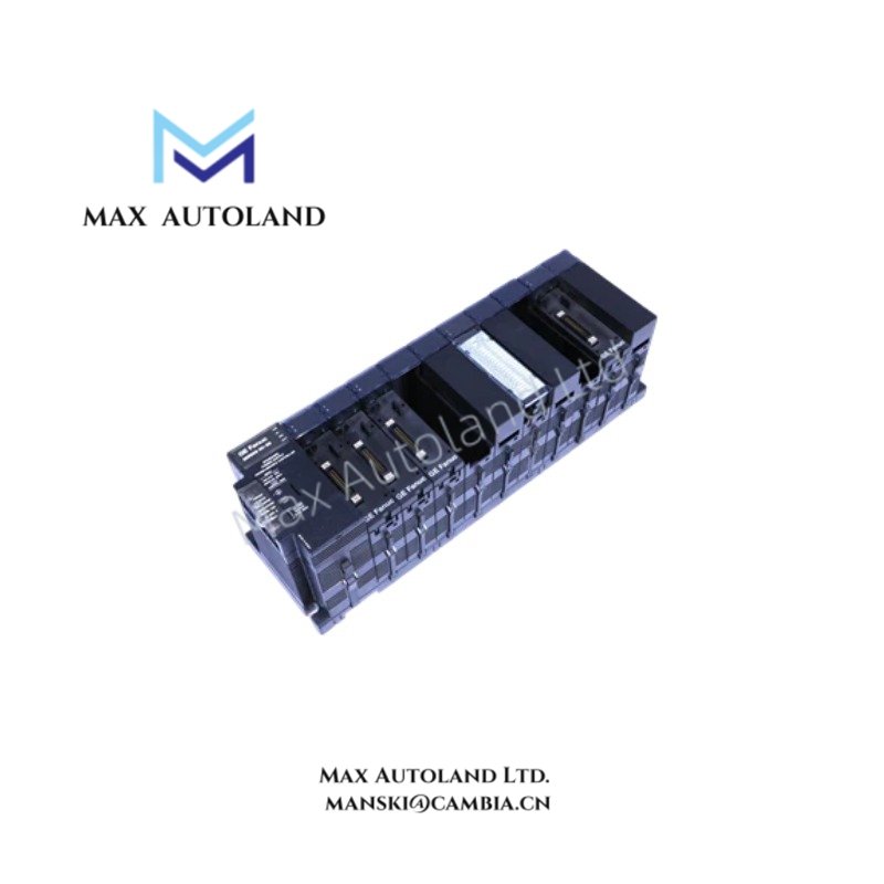
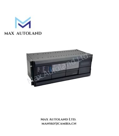
The GE F35E00HCHF8FH6GM8FP6HUXXWXX, also cataloged as the F35 Multiple Feeder Protection System, operates as a dedicated hardware component for feeder protection, control, monitoring, and metering within electrical distribution automation networks. The unit integrates protection elements, programmable logic execution, disturbance recording, communications, and multi-feeder control functions into a single relay platform.
Suffix Breakdown & Model Matrix
The ordering code F35E00HCHF8FH6GM8FP6HUXXWXX represents a factory-defined configuration string used to identify hardware, communication, power supply, I/O, and firmware options.
No official public breakdown for each suffix segment is provided in the supplied documentation. Therefore, individual code positions are not interpreted here.
Hardware Specifications
| Parameter | Specification |
|---|---|
| Model | F35E00HCHF8FH6GM8FP6HUXXWXX |
| Brand | GE Multilin |
| Origin | Not specified in supplied data |
| Weight | Not specified in supplied data |
| Dimensions | Not specified in supplied data |
| Operating Temp | -40 degC to +60 degC |
| Power Consumption | Depends on installed hardware configuration |
| Product Type | Multiple Feeder Protection System |
| Feeder Capacity | Up to 6 feeders; up to 5 feeders with bus voltage measurement |
| Protection Functions | 50P, 50G, 50N, 51P, 51G, 51N, 51SG, 49, 67P, 67G, 67N, 27, 59, 81U, 81O, 25, 79 |
| Autoreclose Elements | Up to 6 |
| Logic Engine | FlexLogic programmable logic |
| Event Recorder | Up to 1024 events with 1 ms resolution |
| Transient Recording | Up to 64 samples per cycle |
| Metering Functions | Current, voltage, power, energy, frequency |
| Communication Protocols | IEC 61850 Edition 1 and Edition 2, Modbus RTU, Modbus TCP, DNP 3.0, R-GOOSE |
| Power Supply Options | 24-48 VDC or 88-300 VDC / 85-264 VAC depending on configuration |
| Interfaces | RS485, Ethernet, RJ45, fiber-optic options |
| Front Protection | IP54 when flush-mounted |
| Compliance | IEEE C37.90, IEC 60255 |
Industrial Ethernet and Firmware Compatibility
As a member of the GE Multilin Universal Relay platform, the F35 supports deterministic substation communication through IEC 61850 messaging, Ethernet-based data exchange, and configurable network architectures. Hardware configurations may include copper or fiber communication interfaces depending on the ordered option set.
Firmware functionality, communication services, and available protection features are dependent on the installed relay firmware revision and ordered hardware configuration. Verification of firmware compatibility should be performed before configuration migration, setting file transfer, or firmware upgrades between relay revisions.
Frequently Asked Questions
Q: Does the F35 support hot-swapping of protection I/O modules while energized?
A: The supplied documentation does not specify hot-swap capability. Module replacement procedures should follow the manufacturer’s maintenance instructions and site lockout requirements.
Q: What communication protocols are available on the relay?
A: Supported protocols include IEC 61850 Edition 1 and Edition 2, Modbus RTU, Modbus TCP, DNP 3.0, and Routable GOOSE (R-GOOSE), subject to the installed communication hardware configuration.
Q: Can the relay perform both protection and control functions simultaneously?
A: Yes. The relay combines protection functions, programmable FlexLogic control execution, metering, event recording, and communication services within a single platform.
Field Installation Guidelines
- Verify control power rating before energization and confirm compatibility with the installed power supply option.
- Maintain separation between CT, VT, communication, and control wiring to reduce electromagnetic coupling.
- Ground cable shields according to substation grounding practices and project engineering standards.
- Confirm CT polarity and VT phasing before commissioning protection elements.
- Validate communication settings, network addressing, and protocol configuration prior to integration with SCADA or station control systems.
- Perform protection setting verification and logic testing before placing feeders into service.
- Review event recorder and disturbance recorder operation during commissioning to confirm correct time synchronization and data capture.