
Overview
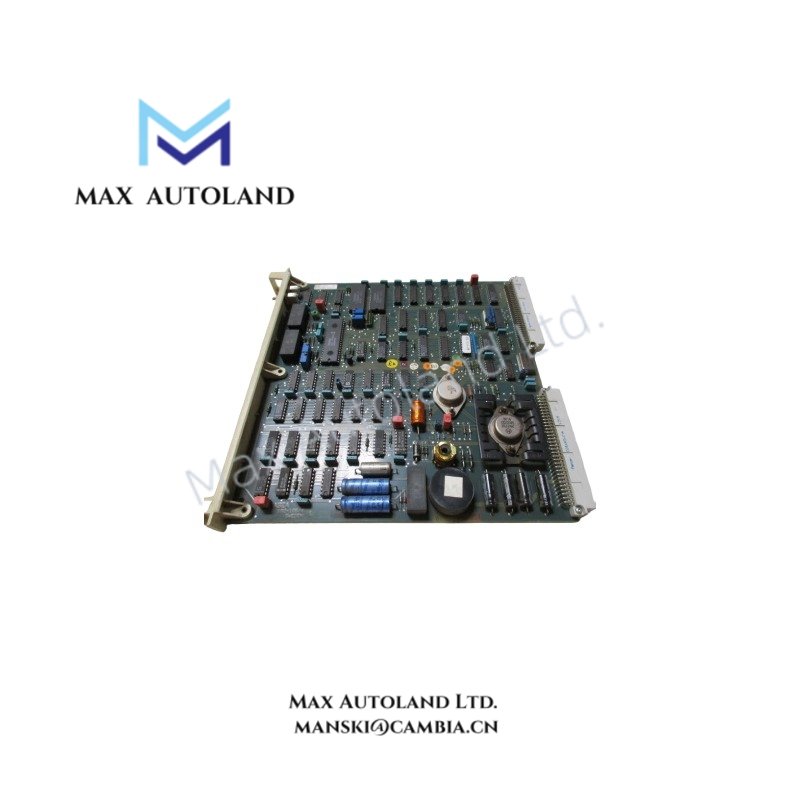
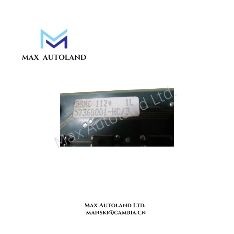
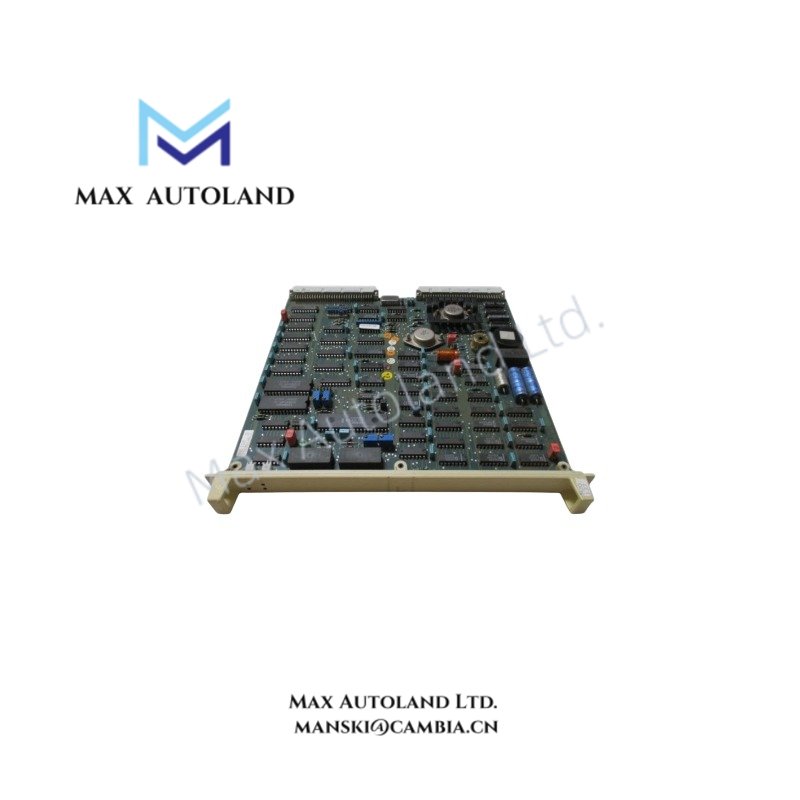
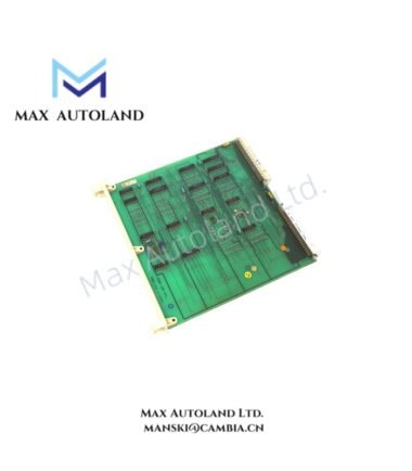
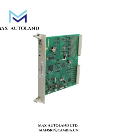
Configured for closed-loop motor drive execution in FlexSK motion networks, the ABB DSMC112 57360001-HC (57360001-HC FlexSK Controller Board) provides direct physical and electrical actuation control. It interfaces with 36 V DC bus-powered motors, translating command signals into precise mechanical movement without auxiliary conversion hardware.
Hardware Specifications
| Parameter | Specification |
|---|---|
| Brand | ABB |
| Model | DSMC112 57360001-HC |
| Origin | Sweden |
| Weight | 0.46 kg |
| Dimensions | 2 x 24.8 x 24.3 cm |
| Operating Temp | 0 degC to +55 degC |
| Storage Temp | -25 degC to +85 degC |
| Power Supply | 24 V DC |
| Current Consumption | <= 0.5 A |
| Motor Output | 36 V DC Bus |
Backplane Bus Communication Velocity Licenses
The module utilizes the FlexSK backplane architecture to manage deterministic data exchange. Communication velocity is governed by firmware flash compatibility with the host controller’s licensing structure. The board requires specific firmware revisions to unlock full bus bandwidth; mismatched firmware results in automatic fallback to reduced polling rates. Electrical isolation between channels prevents propagation of transient noise from the motor bus to the logic backplane.
Frequently Asked Questions
Q: What is the hot-swap limitation for this controller board?
A: Hot-swapping is not supported. Power must be removed from the entire FlexSK segment before inserting or removing the DSMC112 to prevent arcing on the backplane connectors and potential firmware corruption.
Q: Does the current consumption specification include the load?
A: No. The specified <= 0.5 A at 24 V DC refers strictly to the logic supply draw of the controller board itself. The 36 V DC motor bus power is calculated separately based on the connected actuator load.
Q: What are the firmware upgrade compatibility constraints?
A: Firmware flashing must occur within the operating temperature range of 0 degC to +55 degC. Attempting a flash update outside this range may halt the process, rendering the board inoperable until a recovery procedure is executed via the service port.
Field Installation Guidelines
Mount the unit directly to the DIN rail within the designated enclosure, ensuring the locking clip engages fully. Maintain minimum spacing of 10 mm between adjacent modules to allow for adequate airflow across the heat dissipation profile. Route motor power cables (36 V DC) separately from the 24 V DC logic wiring to mitigate electromagnetic interference. Terminate all cable shields at both ends using the chassis ground point to maintain signal integrity. Verify that the 24 V DC supply has reverse polarity protection configured upstream of the module connection.
ABB Top Products
Customers Also Viewed
Contact: Manski Wong +86 18030205725 manski@cambia.cn



Reviews
There are no reviews yet.