")
")
")
Overview
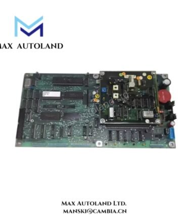
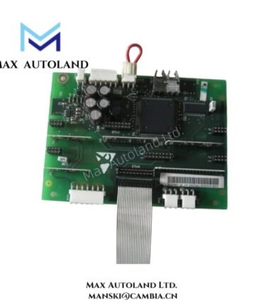
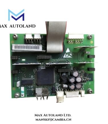
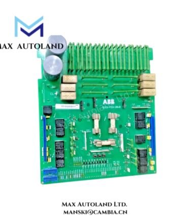
The ABB NBRA-659C, also cataloged as the NBRA-659C Brake Chopper Module, operates as a dedicated hardware component for braking energy dissipation control within ABB drive and power conversion systems. The module monitors DC link voltage conditions and switches braking resistor circuits to absorb regenerative energy generated during motor deceleration events.
Suffix Breakdown & Model Matrix
No official suffix matrix or configurable ordering structure is specified in the available product documentation.
| Parameter | Specification |
|---|---|
| Model Variant | NBRA-659C |
| Description | Brake Chopper Module |
Hardware Specifications
| Parameter | Specification |
|---|---|
| Model | NBRA-659C |
| Brand | ABB |
| Product Type | Brake Chopper Module |
| Function | Dynamic Braking Control |
| Application | DC Link Overvoltage Management |
| Integration | ABB Drive Systems |
| Mounting | Cabinet Installation |
| Origin | ABB Manufacturing Network |
| Weight | Not specified |
| Dimensions | Not specified |
| Operating Temp | Not specified |
| Power Consumption | Not specified |
Firmware Flash Compatibility and System Integration
The NBRA-659C interfaces with ABB drive control architectures through designated drive system connections. Firmware and parameter compatibility must correspond to the associated drive platform revision. During commissioning, the brake chopper configuration, braking resistor characteristics, and drive parameter settings should be verified to ensure correct regenerative energy handling and DC bus voltage regulation.
Frequently Asked Questions
Q: Does the NBRA-659C operate as a standalone braking device?
A: No. The module functions as part of a drive braking system and requires connection to compatible drive hardware and braking resistor assemblies.
Q: Can the module be replaced while the drive system remains energized?
A: Cabinet power isolation is recommended before removal or installation. Hot-swap capability is not specified in the available documentation.
Q: What should be checked after installation?
A: Verify wiring continuity, resistor connections, grounding integrity, and drive parameter configuration before enabling operation.
Field Installation Guidelines
- Isolate all incoming power sources before installation or maintenance activities.
- Mount the module according to the cabinet layout specified for the associated ABB drive platform.
- Route braking resistor conductors separately from low-level control and communication cables.
- Maintain proper protective grounding for the module enclosure and resistor assembly.
- Confirm conductor sizing and terminal torque values according to system engineering documentation.
- Inspect insulation condition of braking resistor wiring before energization.
- Perform functional testing under controlled deceleration conditions to verify braking operation.
ABB Top Products
Customers Also Viewed
Contact: Manski Wong +86 18030205725 manski@cambia.cn


Reviews
There are no reviews yet.