
Overview
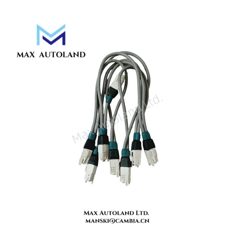
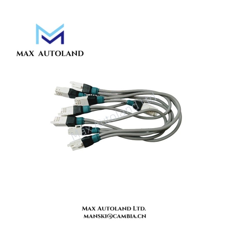
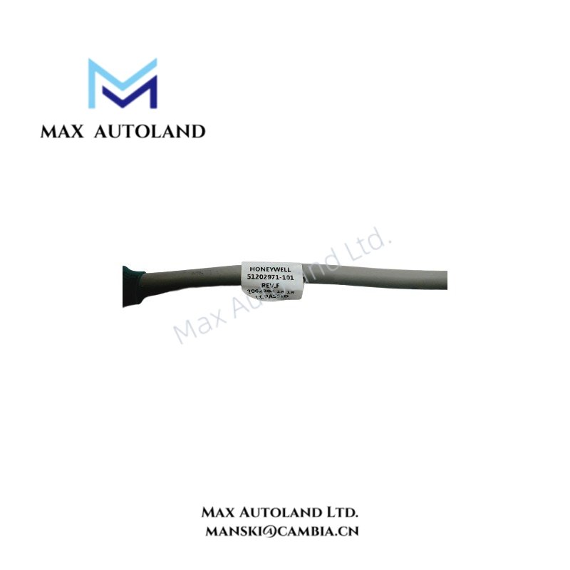
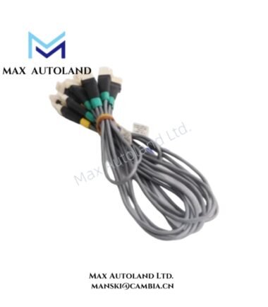
The Honeywell 51202971-101, also cataloged as the 51202971-101 I/O Link Cable Assembly, operates as a dedicated hardware component for multi-drop communication routing within Honeywell Experion LX Series 8 control systems. Specifically serving as Cable B in the Series 8 I/O Link 1 (IOL1) architecture, this assembly establishes physical interconnection links between compatible I/O termination assemblies (IOTAs) and system header boards inside industrial control enclosures.
Hardware Specifications
| Parameter | Specification |
|---|---|
| Model | 51202971-101 |
| Brand | Honeywell |
| Origin | Verified Industrial Supplier Stock |
| Weight | Not independently verified |
| Dimensions | 6-inch (152 mm) drop pitch; overall length variable per cabinet installation |
| Operating Temp | Standard industrial control cabinet limits (0 deg C to 60 deg C) |
| Power Consumption | Passive cabling assembly (0 W active draw) |
| Product Type | I/O Link Cable Assembly |
| Product Series | Series 8 |
| Cable Classification | I/O Link 1 (IOL1) |
| Cable Designation | Cable B |
| Cable Color | Gray |
| Identification Label | Green |
| Number of Drops | 6 drops |
4-20 mA HART Loop Protocol & I/O Interconnection
The assembly facilitates multi-drop signal transmission while maintaining channel-to-channel signal integrity across process control modules. Because it operates within Honeywell Experion LX architectures, the cabling layout supports analog input/output loops utilizing 4-20 mA HART protocol and discrete signals routed through system header boards. Technicians must ensure that cable routing avoids high-voltage electromagnetic interference (EMI) paths to preserve data transmission rates over the Series 8 backplane infrastructure.
Frequently Asked Questions
Q: What distinguishes the 51202971-101 from the 51202971-100 cable assembly?
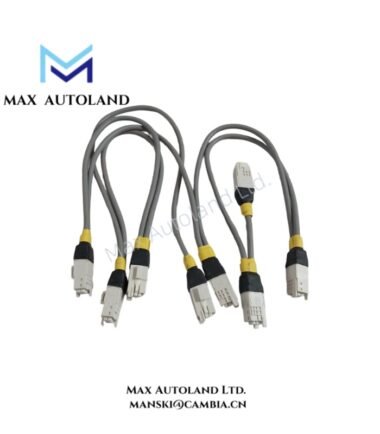
A: While both assemblies feature a six-drop configuration and a 152 mm drop pitch, the 51202971-101 utilizes a green identification label and functions as Cable B, whereas the 51202971-100 features a yellow label and acts as Cable A.
Q: Can this cable assembly be hot-swapped during active process control operations?
A: No, disconnecting or replacing active I/O Link cabling while the control system is powered on can disrupt communication on the Series 8 link, potentially triggering fault states in the C300 controller subsystem. Always de-energize the affected IOTA segment prior to maintenance.
Q: How is redundant link communication achieved using these assemblies?
A: Redundancy is implemented by installing Cable A (51202971-100) alongside Cable B (51202971-101) as a matched pair (ordered together as 51202971-102) to establish parallel, fault-tolerant communication paths between the controller and I/O modules.
Field Installation Guidelines
- Verify that the control cabinet power is completely switched off before handling any internal cabling or I/O termination assemblies.
- Inspect the green identification labels on the 51202971-101 assembly to confirm it matches the designated Cable B connection port on the system header board.
- Secure each drop connector sequentially, maintaining the 6-inch (152 mm) pitch alignment to prevent mechanical strain on the IOTA terminals.
- Route the gray cable jacket through designated wire management channels, ensuring adequate physical separation from AC power conduits and high-frequency drive cables.
- Fasten all retaining screws on the connector plugs to standard torque limits to ensure reliable contact resistance before restoring system power.
Reviews
There are no reviews yet.