


Overview
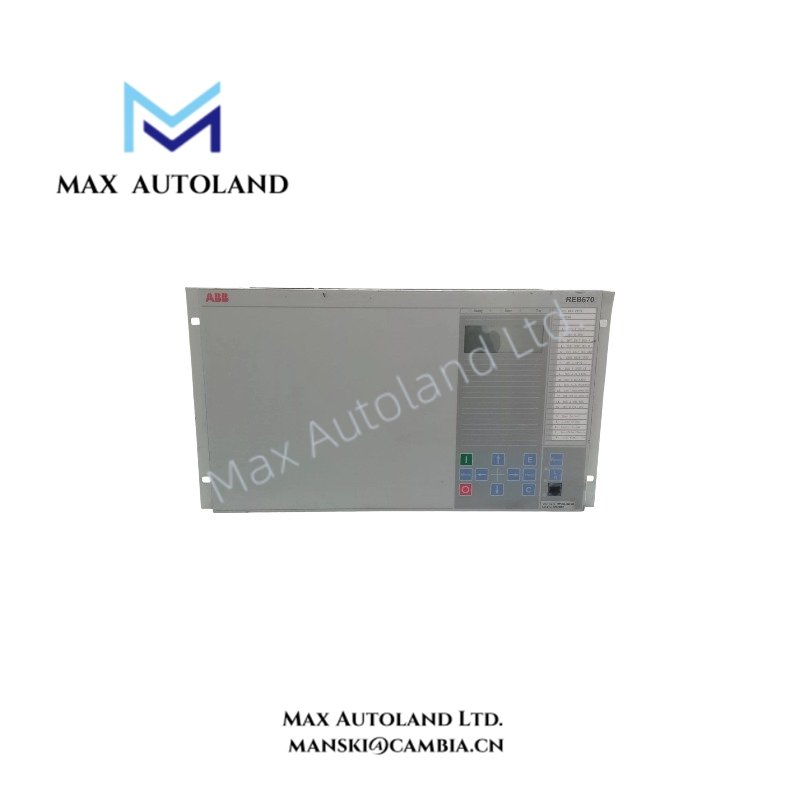
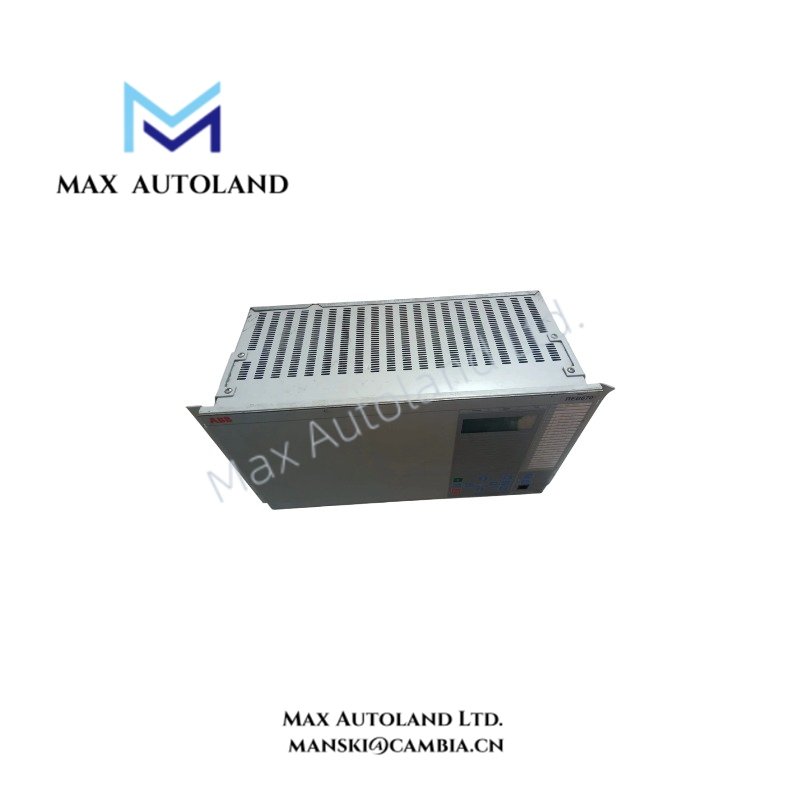
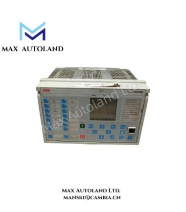
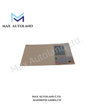
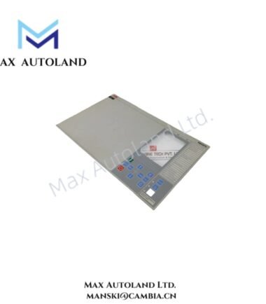
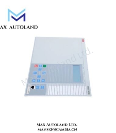
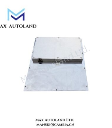
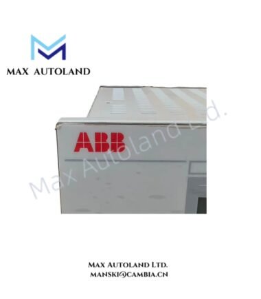
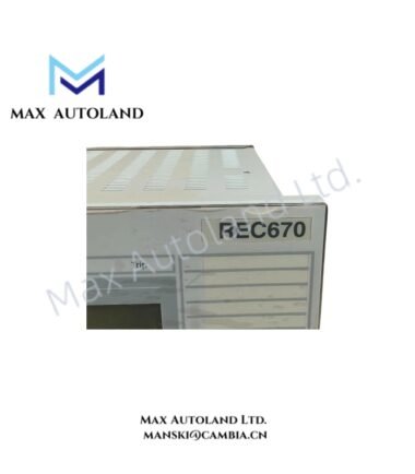
The ABB REB670, also cataloged as the REB670 busbar protection relay, processes current transformer (CT) signals to detect internal busbar faults and initiate selective circuit breaker tripping. It uses low-impedance differential protection and configurable busbar zone selection to evaluate current distribution across connected bays. The relay supports substation configurations with multiple busbars and changing disconnector positions.
Hardware Specifications
| Parameter | Specification |
|---|---|
| Model | REB670 |
| Brand | ABB |
| Product Type | Busbar Protection Intelligent Electronic Device (IED) |
| Protection Principle | Low-impedance differential protection |
| Rated Frequency | 50 / 60 Hz |
| Rated Current | 1 A or 5 A |
| Continuous Current Withstand | 4 x Ir |
| Current Withstand for 1 Minute | 10 x Ir |
| Current Withstand for 10 Seconds | 30 x Ir |
| Current Withstand for 1 Second | 100 x Ir |
| Dynamic Current Withstand | 250 x Ir for one half-wave |
| Input Burden | Less than 20 mVA at 1 A; less than 150 mVA at 5 A |
| Auxiliary Power Supply | Configuration-dependent; examples include 24-60 VDC and 90-250 VDC |
| Power Consumption | Approximately 50 W, as provided in the source description |
| Binary Input Voltage | Configuration-dependent; options include 24/30 V, 48/60 V, 110/125 V and 220/250 VDC |
| Communication Protocols | IEC 61850-8-1, DNP3, IEC 60870-5-103, LON and SPA, depending on hardware and configuration |
| Optical Communication | Local Data Communication Module (LDCM), depending on configuration |
| Configuration Software | ABB PCM600 with the applicable Connectivity Package |
| Housing | Rack formats vary by hardware configuration |
| Dimensions | Full 19-inch enclosure example: 483 x 132 x 215 mm |
Note: The listed electrical ratings and enclosure dimensions must be checked against the exact REB670 hardware variant and product documentation before installation.
Busbar Differential Protection and Zone Selection
The REB670 compares CT measurements from connected bays to identify differential current associated with internal busbar faults. Its configured busbar replica uses switchgear position information to assign bays to the corresponding protection zones.
For external faults, the differential protection logic must remain stable when high through-fault currents cause CT saturation. The supplied description also identifies open CT secondary circuit detection and associated blocking logic. Actual protection functions depend on the selected application configuration, hardware and firmware.
For station communication, IEC 61850-8-1 can support GOOSE messaging between compatible devices. LDCM interfaces can support inter-relay data exchange where the selected hardware and system configuration provide that functionality.
Frequently Asked Questions (FAQ)
Q: Which CT secondary current ratings does the REB670 support?
A: The supplied specifications identify 1 A and 5 A CT secondary ratings. Verify the selected analog input hardware and approved wiring configuration before connecting CT circuits.
Q: Can the REB670 operate in a double-busbar substation?
A: The described applications include single and double busbar arrangements, including configurations with transfer bus sections. Correct operation depends on the configured busbar replica, switchgear status inputs and protection application.
Q: Which software is used to configure the REB670?
A: ABB PCM600 is identified as the engineering tool. The applicable Connectivity Package and compatible device configuration must match the installed relay version.
Field Installation Guidelines
- Verify the complete relay ordering code, hardware variant, auxiliary supply rating and approved terminal diagrams before installation.
- Install the relay in the specified panel or rack arrangement. Confirm enclosure dimensions, ventilation clearances and mechanical support against the applicable ABB installation manual.
- Connect CT secondary circuits according to the approved protection drawings. Maintain correct polarity and phase identification, and never leave an energized CT secondary circuit open.
- Separate CT wiring from high-current power conductors and switching circuits where practicable. Apply the panel’s documented shielding and protective earthing arrangements.
- Verify binary input voltage levels and trip output contact ratings against the connected switchgear interface.
- Confirm IEC 61850 network settings, GOOSE subscriptions and inter-relay communication paths where these functions are used.
- Test CT polarity, differential protection stability, zone selection, trip logic and external-fault response under an approved commissioning procedure before placing the protection scheme in service.
ABB Top Products
Customers Also Viewed
Contact: Manski Wong +86 18030205725 manski@cambia.cn





Reviews
There are no reviews yet.