
Overview
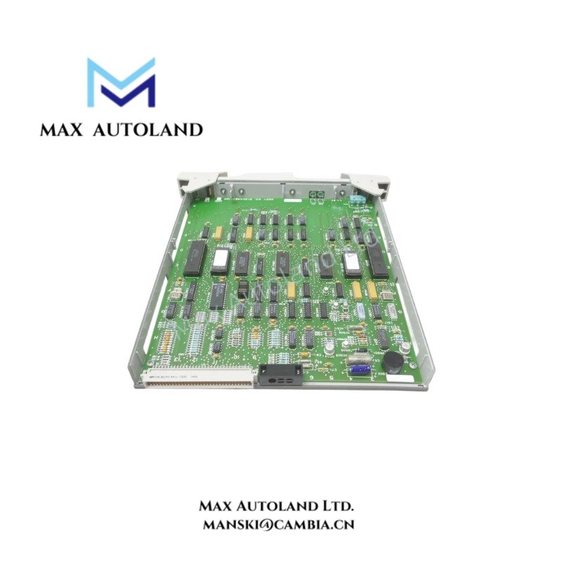
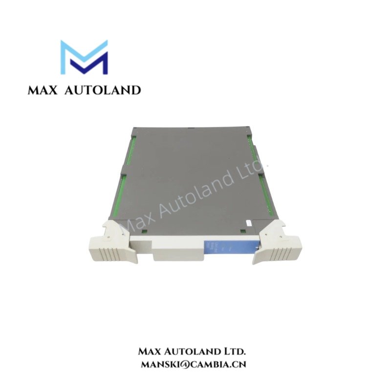
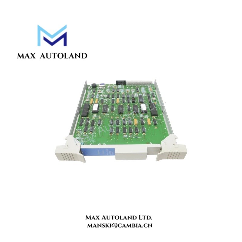
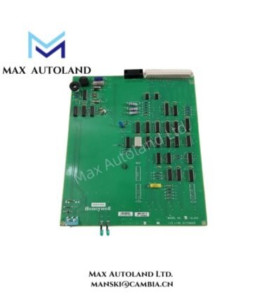
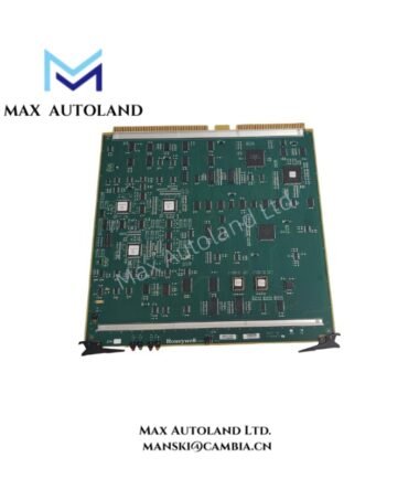
The Honeywell 51304481-100, also cataloged as the 51304481-100 Low-Level Analog Input IOP Module, operates as a dedicated hardware component for low-level analog signal acquisition within Honeywell TDC 3000 and TPS control system architectures.
Hardware Specifications
| Parameter | Specification |
|---|---|
| Model | 51304481-100 |
| Brand | Honeywell |
| Origin | USA |
| Weight | Approximately 0.45 kg |
| Dimensions | 112 x 90 x 60 mm |
| Operating Temp | Standard industrial enclosure range |
| Power Consumption | Powered via system backplane / card file |
| Input Signal Type | Millivolt-level analog signals / Thermocouples |
| System Series | Honeywell TDC 3000 / TPS |
Cold Junction Compensation and Signal Isolation
Executing accurate thermocouple measurements requires rigorous compensation methodologies. The Honeywell 51304481-100 incorporates specialized cold junction compensation (CJC) circuitry to reference ambient terminal temperature against thermocouple voltage curves, thereby eliminating thermal drift errors at the termination interface. Furthermore, channel conditioning circuitry maintains rigorous electrical isolation barriers to mitigate common-mode noise and ground loops inherent in heavy industrial environments. Field-originated millivolt signals traverse dedicated analog-to-digital conversion paths, ensuring high measurement fidelity before transmission across the backplane bus to the host controller.
Frequently Asked Questions
Q: Does the module support online hot-swapping during active system operations?
A: Hot-insertion capabilities depend strictly on the specific card file architecture and controller rack design of the installed TDC 3000 or TPS node. Verify rack power status and system documentation before replacing hardware.
Q: How does the module handle thermocouple open-circuit detection?
A: The input circuitry incorporates diagnostic bias current sensing to detect open-circuit thermocouple loops, immediately signaling an alarm state to the host processor upon signal discontinuity.
Field Installation Guidelines
- Verify the complete part number and suffix, including the -100 designation, against system engineering drawings prior to physical insertion.
- Ensure all power to the target card slot is isolated to prevent electrical transients or bus contention during module installation.
- Route low-level analog and thermocouple extension cables through dedicated grounded conduits, maintaining strict separation from high-voltage power lines.
- Secure shield drain wires exclusively at the designated system grounding bar to eliminate electromagnetic interference.
- Inspect terminal blocks and termination assembly hardware for oxidation, mechanical wear, or loose wiring before powering up the subsystem.
- Execute channel diagnostics and calibration verification routines through the system engineering station after successful installation.





Reviews
There are no reviews yet.