
Overview
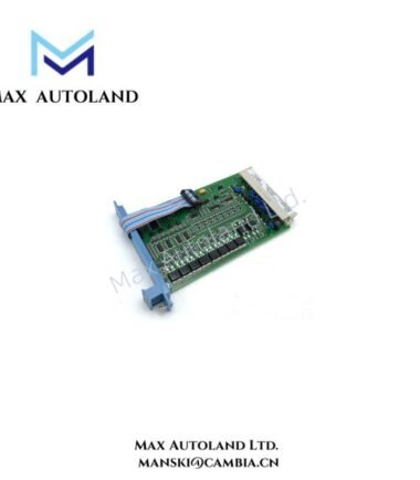
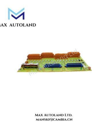
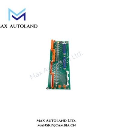
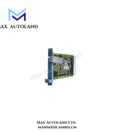
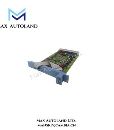
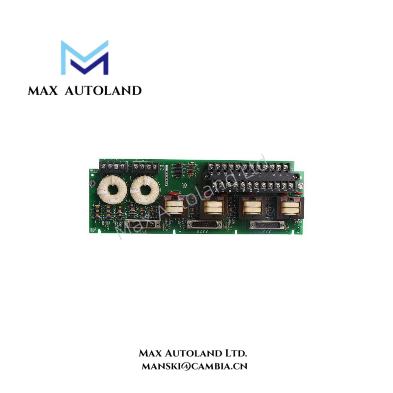
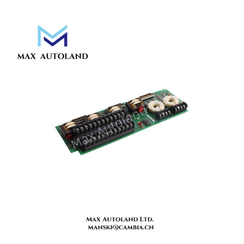
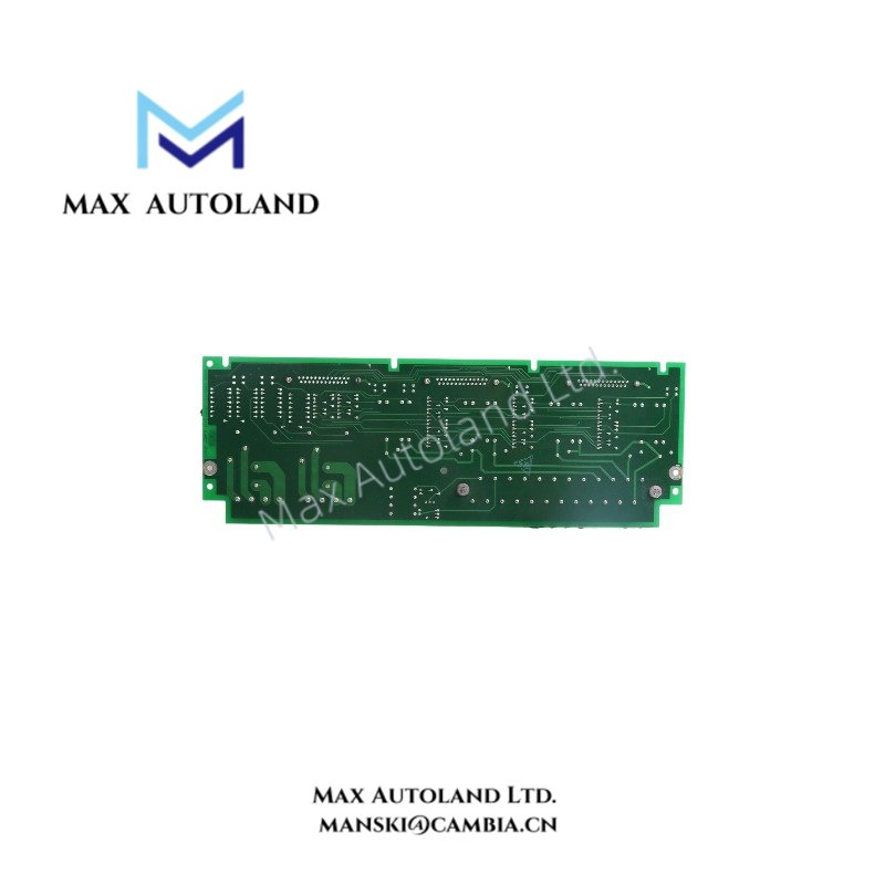
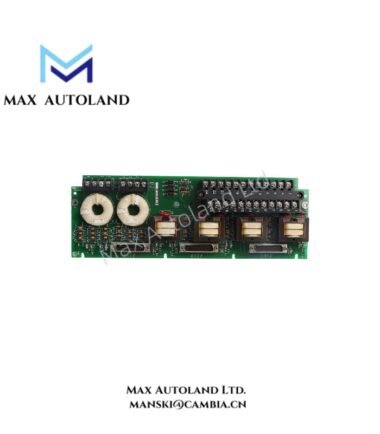
Configured for analog processing within the GE Mark VI platform, the GE IS210BAPAH1A (IS210BAPAH1A Analog Processor Module) provides a VME card format for system-level signal processing. The supplied data specifies 125 VDC input and 24 VDC output operation, with a -30 to +65 deg C operating range.
Hardware Specifications
| Parameter | Specification |
|---|---|
| Model | IS210BAPAH1A |
| Brand | General Electric |
| Series | Mark VI |
| Product Type | Analog Processor Module |
| Module Format | VME Card |
| Model Type | Safety I/O Pack |
| Origin | USA |
| Weight | 0.38 kg |
| Dimensions | 4.1 x 16.5 x 25.5 cm estimated shipping size |
| Input Voltage | 125 VDC |
| Output Voltage | 24 VDC |
| Operating Temp | -30 to +65 deg C |
| Mounting | DIN-rail |
| Power Consumption | Not specified in supplied data |
| Tariff Code | 8537101190 |
| Shipment Origin | Xiamen, China |
GE Industrial Control Interface Characteristics
The IS210BAPAH1A is identified as a GE Mark VI Analog Processor Module in VME card format. The supplied specifications define the electrical voltage values and environmental operating range, but they do not provide detailed backplane bus speed, channel count, firmware compatibility, or communication protocol data.
Therefore, these parameters should be verified against the applicable GE Mark VI system documentation before system integration. The supplied mounting specification identifies DIN-rail mounting, while the stated dimensions represent the estimated shipping size rather than confirmed board dimensions.
Frequently Asked Questions
Q: What input and output voltages are specified for the IS210BAPAH1A?
A: The supplied data specifies 125 VDC input voltage and 24 VDC output voltage.
Q: What operating temperature range is specified?
A: The specified operating range is -30 to +65 deg C.
Q: Does the supplied data specify power consumption or VME bus communication parameters?
A: No. The supplied information does not define power consumption, VME bus speed, communication protocol, or backplane current requirements.
Field Installation Guidelines
Install the module according to the applicable GE Mark VI hardware documentation and the equipment cabinet requirements.
Verify the module identification before installation. Confirm that the electrical supply matches the specified 125 VDC input requirement and that connected circuits are compatible with the stated 24 VDC output.
For DIN-rail installation, secure the module mechanically before connecting field wiring. Route power and signal conductors separately where practical to reduce electrical interference. Maintain proper conductor insulation and terminal clearance.
Connect protective and signal grounding according to the cabinet grounding scheme and applicable installation standards. Do not assume undocumented pin assignments, connector functions, VME bus parameters, or circuit protection values. Verify these details from the specific system documentation before energizing the module.