
Overview
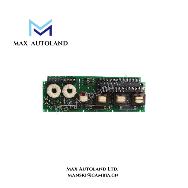
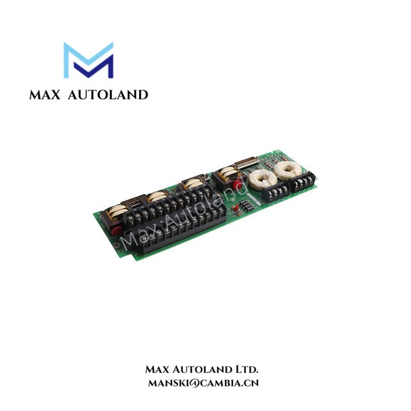
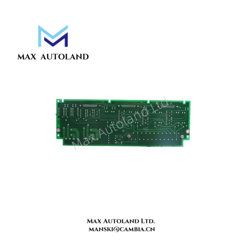
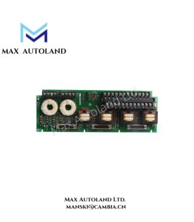
Configured for voltage and current signal acquisition in the GE Mark VI EX2100 excitation system, the GE IS200EPCTG1A (IS200EPCTG1A Exciter PT/CT Board) accepts 120 VAC voltage input and 1 A or 5 A current input. It operates across a 45 Hz to 65 Hz frequency range and provides PT/CT signal interfacing.
Hardware Specifications
| Parameter | Specification |
|---|---|
| Model | IS200EPCTG1A |
| Spare Model | IS200EPCTG1A |
| Brand | General Electric |
| Series | Mark VI / EX2100 |
| Product Type | Exciter PT/CT Board |
| Function | Input/Output Terminal Board |
| Origin | USA |
| Weight | 0.98 kg |
| Dimensions | 33.1 x 11.5 x 4.5 cm estimated shipping size |
| Operating Temp | -30 deg C to +70 deg C |
| Power Consumption | Not specified in supplied data |
| Voltage Input | 120 VAC |
| Current Input | 1 A or 5 A |
| Frequency Range | 45 Hz to 65 Hz |
| Phase Error | < 0.3 deg at 50/60 Hz |
| Signal Range | 0-10 V or 4-20 mA |
| Tariff Code | 8537101190 |
| Shipment Location | Xiamen, China |
GE Mark VI EX2100 Signal Interface
The IS200EPCTG1A processes PT/CT-related electrical input signals within the Mark VI EX2100 architecture. The board accepts a 120 VAC voltage input and supports 1 A or 5 A current input.
The specified frequency range is 45 Hz to 65 Hz. The phase error remains below 0.3 deg at 50/60 Hz according to the supplied specifications. In addition, the listed signal range includes 0-10 V and 4-20 mA interfaces.
For industrial control integration, the board therefore handles electrical measurement signals before associated control and excitation functions process the available data. Installation should maintain correct separation between power conductors and low-level signal wiring.
Frequently Asked Questions
Q: What voltage input does the IS200EPCTG1A accept?
A: The specified voltage input is 120 VAC.
Q: What current input ranges are specified?
A: The board supports 1 A or 5 A current input.
Q: What frequency range does the board support?
A: The specified operating frequency range is 45 Hz to 65 Hz.
Field Installation Guidelines
- Verify the complete IS200EPCTG1A model number before installation.
- Confirm the voltage and current wiring against the applicable GE Mark VI EX2100 documentation.
- Connect 120 VAC voltage inputs only to the designated terminals.
- Verify whether the installation requires the 1 A or 5 A current-input configuration.
- Route current, voltage, and low-level signal wiring according to the cabinet wiring design.
- Keep signal wiring separated from high-energy switching and power conductors where practical.
- Verify terminal identification and conductor polarity before energizing the circuit.
- Inspect all terminal connections for secure mechanical engagement.
- Apply appropriate grounding and shielding practices to 0-10 V and 4-20 mA signal wiring.
- Perform continuity and wiring verification before commissioning the board.


