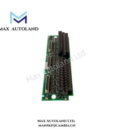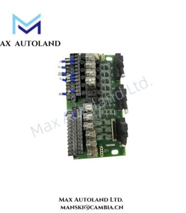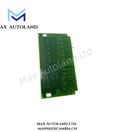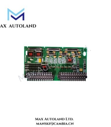

Overview
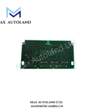
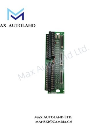
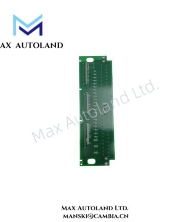
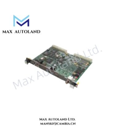
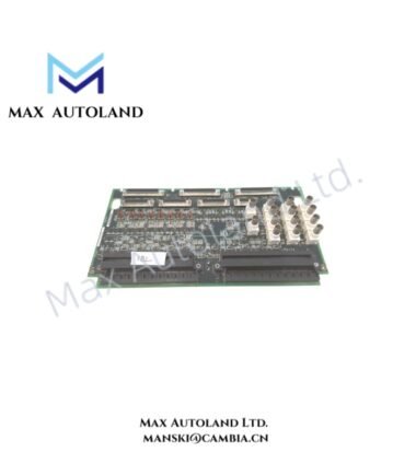
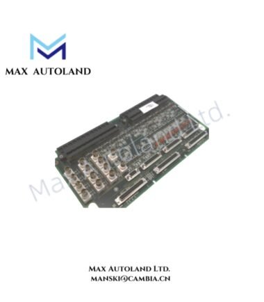
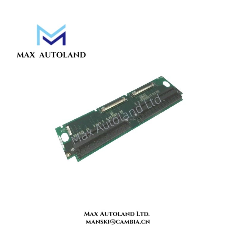
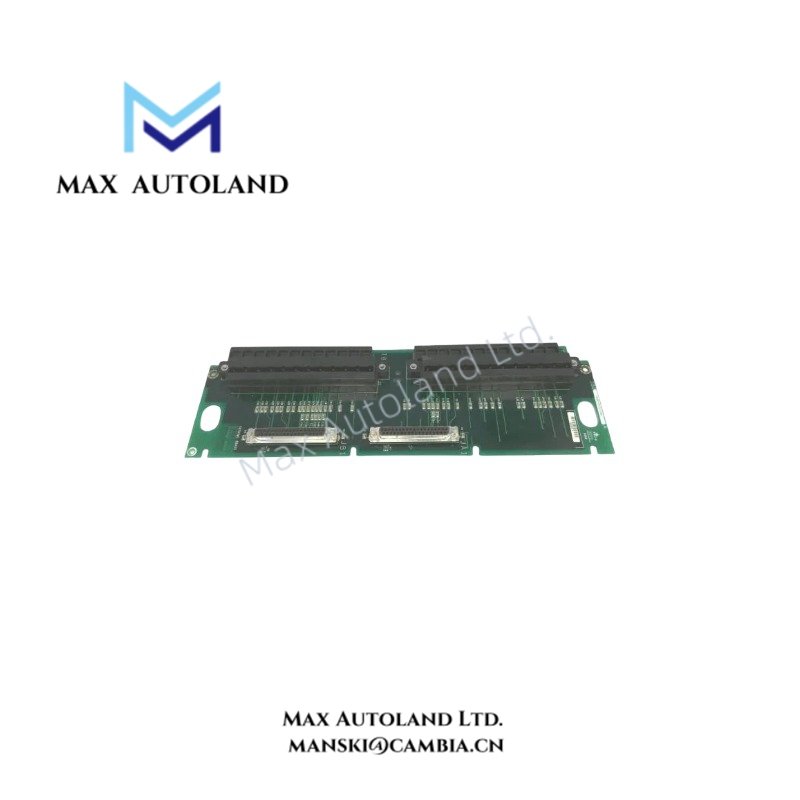
The GE IS200TRTDH1C, also identified by the base model IS200TRTDH1C, is an RTD Input Terminal Board designed to interface resistance temperature detector (RTD) signals with GE turbine control I/O processors. It provides field wiring termination, multiplexed excitation current, and input signal conditioning for temperature measurement. The board uses two terminal blocks for RTD field connections and DC-type connectors for interfacing with compatible VRTD boards.
Hardware Specifications
| Parameter | Specification |
|---|---|
| Model | IS200TRTDH1C |
| Brand | General Electric (GE) |
| Series | Mark VIe (as supplied) |
| Product Type | RTD Input Terminal Board |
| Input Channels | 16 RTD inputs, three-wire |
| Terminal Blocks | 2 barrier-type terminal blocks |
| RTD Excitation Current | 10 mA DC, multiplexed |
| Input Signal Processing | RTD signal conditioning and multiplexing |
| Input Voltage | 125 V (supplied specification; application requires verification) |
| Total Output | 400 W (supplied specification; not independently verified) |
| Operating Temperature | 0 to 60 deg C |
| Board Dimensions | 6.25 x 4.25 in |
| Estimated Shipping Dimensions | 43.3 x 28 x 3.5 cm |
| Weight | 1.5 kg |
| Origin | USA |
| Manual | GEH-6421L |
RTD Signal Acquisition and I/O Processing
The IS200TRTDH1C accepts three-wire RTD signals through two barrier-type terminal blocks. Its input circuitry provides high-frequency noise decoupling and surge-related signal conditioning. Compatible I/O processors supply multiplexed excitation current, sample the RTD signals, convert measurements into digital values, and apply software linearization for supported RTD types.
The supplied technical description identifies the following operating characteristics:
- Excitation: 10 mA DC multiplexed current per RTD.
- Input wiring distance: Up to 300 m, subject to the specified cable resistance and installation conditions.
- Signal monitoring: Out-of-range measurements can indicate open or shorted RTD circuits.
- Channel recovery: The description specifies automatic restoration after approximately 20 seconds for recovered channels, with manual restoration also available.
- Signal routing: The H1C version uses two DC-type connectors for VRTD interfacing.
The description also refers to normal-scan and quick-scan operation. Confirm the supported scan mode and compatible I/O processor configuration against the applicable GE manual before installation.
Frequently Asked Questions
Q: How many RTD sensors can the IS200TRTDH1C accommodate?
A: The supplied functional description specifies 16 three-wire RTD inputs connected through two barrier-type terminal blocks.
Q: Does the IS200TRTDH1C provide continuous RTD excitation?
A: No. The supplied description specifies a multiplexed 10 mA DC excitation current rather than continuous excitation.
Q: Can the board identify open or shorted RTD wiring?
A: The described input monitoring can detect measurements outside hardware limits, including conditions associated with open or shorted RTD circuits. Confirm diagnostic behavior and channel recovery procedures for the installed configuration.
Field Installation Guidelines
- Verify system compatibility: Confirm the board revision, controller platform, connector arrangement, and associated VRTD interface against GE documentation before installation.
- Connect RTD wiring: Terminate the three-wire RTD circuits at the designated terminal positions. Follow the terminal assignments in the applicable wiring diagram.
- Ground cable shields: Use the designated shield terminal strip and chassis-ground arrangement. Avoid unintended grounding paths that may introduce measurement noise.
- Route field wiring: Separate low-level RTD signal cables from high-voltage conductors, switching circuits, and other sources of electromagnetic interference.
- Check cable resistance: Verify the total cable resistance and installation distance against the applicable hardware limits before commissioning.
- Inspect connectors: Confirm that terminal blocks and DC-type connectors are correctly seated and secured before applying power.
- Validate measurements: After installation, compare controller readings with reference temperature measurements and check for open-circuit, short-circuit, or out-of-range diagnostics.