

Overview
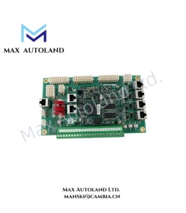
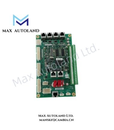
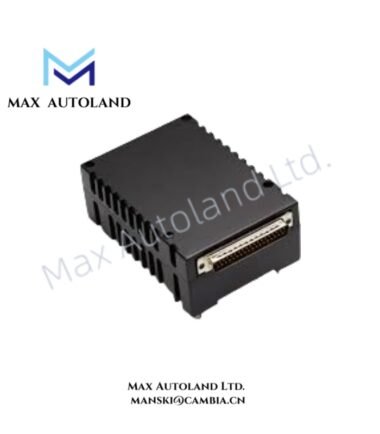
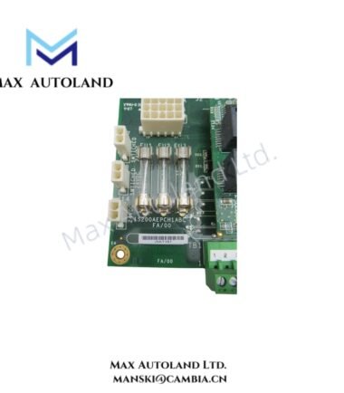
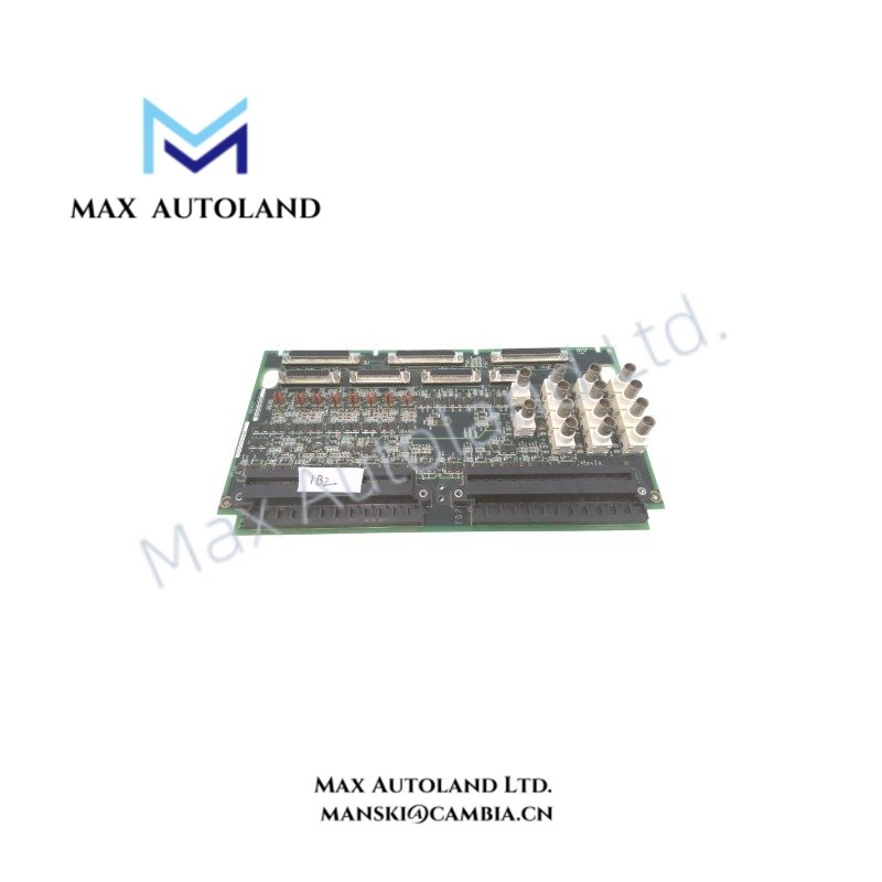
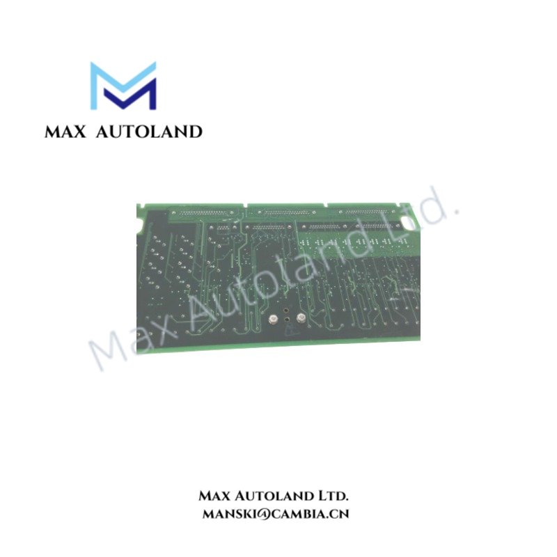
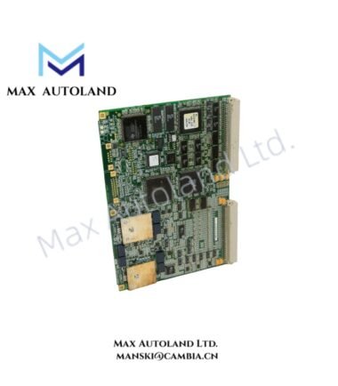
Configured for vibration signal termination and solenoid interface execution in the GE Mark VI control system, the GE IS200TVIBH2BBB (IS200TVIBH2B Vibration Terminal Board) provides direct physical and electrical signal routing for turbine monitoring circuits.
Hardware Specifications
| Parameter | Specification |
|---|---|
| Model | IS200TVIBH2BBB |
| Spare Model | IS200TVIBH2B |
| Brand | General Electric (GE) |
| Series | Mark VI |
| Product Type | Vibration Terminal Board |
| Origin | USA |
| Weight | 0.84 kg |
| Dimensions | 33 x 17.8 x 4.5 cm |
| Operating Temp | 0 to 60 deg C |
| Power Consumption | Passive terminal board; power consumption depends on connected field circuits |
| Number of Channels | 13 channels |
| Trip Solenoids | 3 |
| Solenoid Rated Voltage/Current | 125 VDC |
| Tariff Code | 8537101190 |
Industrial Control Signal Termination Features
The IS200TVIBH2BBB supports vibration monitoring signal termination within GE Mark VI turbine control architectures. The board provides field wiring interfaces for vibration inputs and trip solenoid circuits, while maintaining defined electrical separation between connected devices.
The vibration interface design supports turbine condition monitoring applications where signal integrity depends on correct field wiring, shielding, and grounding practices. In addition, the terminal board configuration allows integration with Mark VI I/O modules for vibration acquisition and protective shutdown functions.
GE Mark VI systems use structured backplane communication and I/O density scaling methods to coordinate control, protection, and monitoring modules. Therefore, the IS200TVIBH2BBB operates as a field termination component rather than an independent processing unit.
Frequently Asked Questions
Q: Does the IS200TVIBH2BBB perform vibration signal processing internally?
A: No. The IS200TVIBH2BBB functions as a vibration terminal board and provides field termination interfaces. The connected Mark VI I/O hardware performs signal conditioning and processing.
Q: How many vibration channels and trip solenoid circuits does this board support?
A: The board supports 13 vibration-related channels and provides connections for 3 trip solenoids rated at 125 VDC.
Q: What installation practices apply to vibration signal wiring?
A: Installers should maintain proper cable shielding, separate low-level vibration signal wiring from high-power conductors, and verify terminal connections before system operation.
Field Installation Guidelines
- Mount the terminal board according to the Mark VI cabinet mechanical arrangement and verify connector alignment before installation.
- Use approved field wiring methods for vibration inputs and solenoid circuits to prevent signal interference.
- Connect cable shields according to the system grounding design and avoid creating unintended ground loops.
- Route vibration signal cables separately from high-current switching lines to reduce electromagnetic interference.
- Verify terminal identification and field device polarity before energizing connected circuits.
- Inspect all wiring points after installation because loose terminals can affect vibration measurement accuracy and trip circuit operation.