

Overview
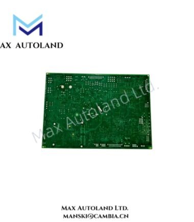
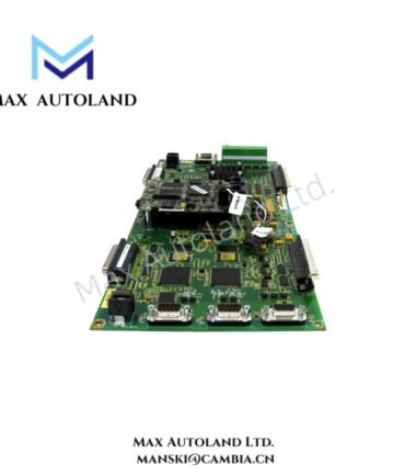
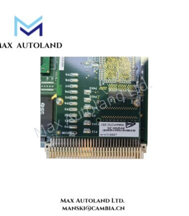
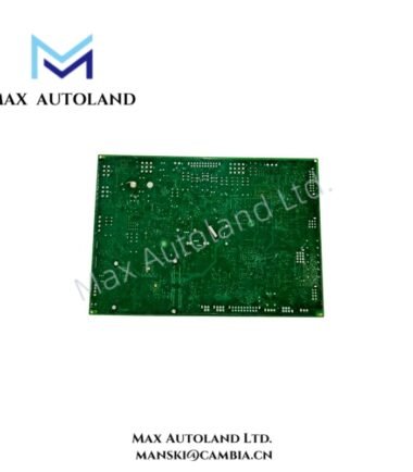
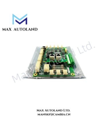
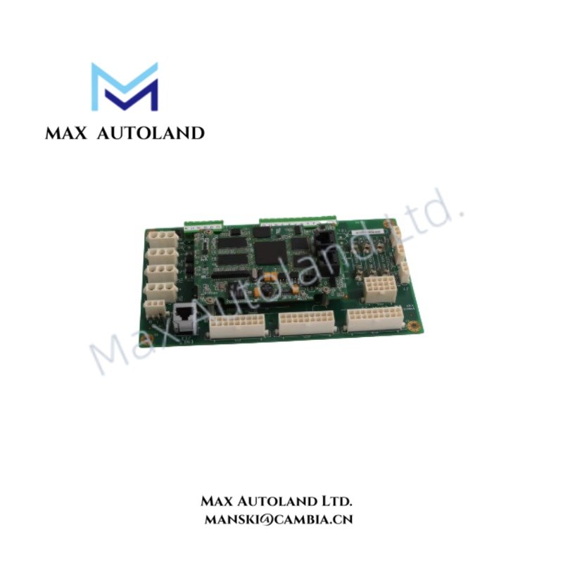
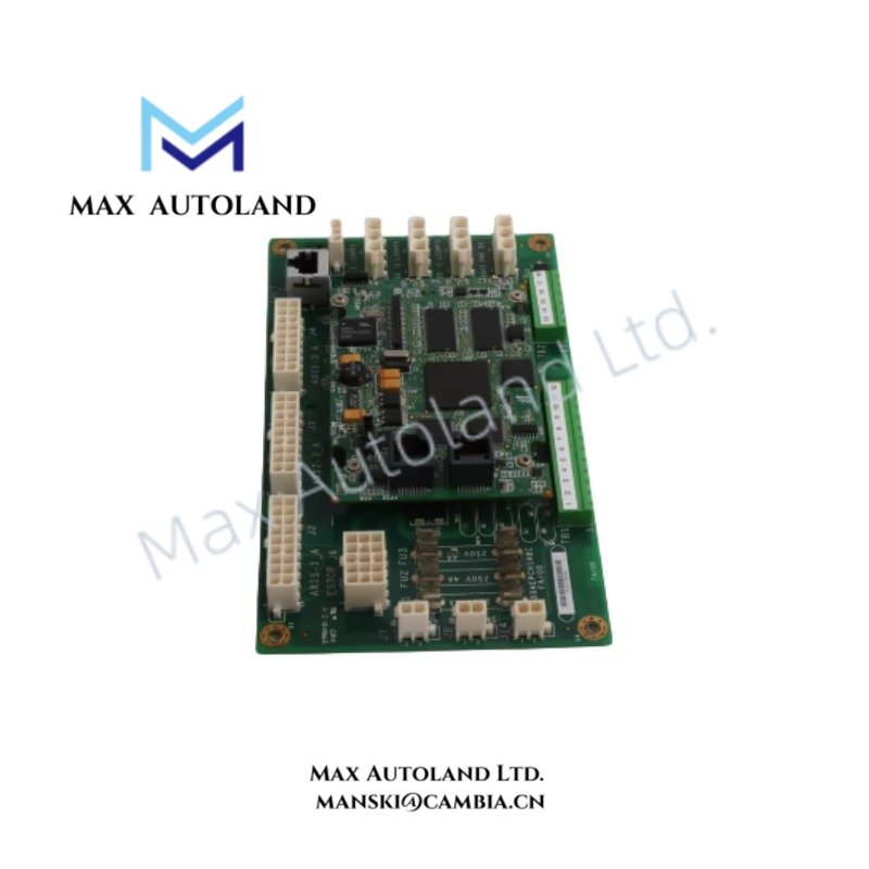
Configured for physical I/O signal processing in the GE Mark VI control system, the GE IS200BPPBH2BJD (IS200BPPBH2B Circuit Board) provides direct electrical execution for BPPC-based I/O pack interfaces.
Hardware Specifications
| Parameter | Specification |
|---|---|
| Model | IS200BPPBH2BJD |
| Brand | General Electric |
| Product Type | Mark VI BPPC I/O Pack Circuit Board |
| System Platform | GE Mark VI Control System |
| Spare Model | IS200BPPBH2B |
| Circuit Function | BPPC-based I/O pack interface hardware |
| Origin | USA |
| Weight | 0.05 kg |
| Dimensions | 11 x 7.5 x 2.2 cm |
| Tariff Code | 8537101190 |
| Shipment Location | Xiamen, China |
Backplane Bus Communication and I/O Density Scaling
The IS200BPPBH2BJD operates as a printed circuit board component within the GE Mark VI architecture. It supports BPPC-based I/O pack connections and provides the electrical interface required for control system data exchange.
Furthermore, the board follows GE industrial control hardware design principles for backplane bus communication velocity and modular I/O density scaling. The physical interface maintains signal continuity between control modules and connected I/O processing units.
The board does not contain field device terminals directly. Instead, it functions as an internal hardware layer that supports communication and signal routing between Mark VI system components.
Frequently Asked Questions
Q: What is the primary function of the GE IS200BPPBH2BJD?
A: The IS200BPPBH2BJD functions as a Mark VI BPPC-based I/O pack circuit board. It provides internal electrical interfacing for I/O pack communication within the control system.
Q: Can the IS200BPPBH2BJD operate as a standalone controller?
A: No. The board operates as part of the GE Mark VI hardware architecture and requires integration with compatible control system components.
Q: Does the IS200BPPBH2BJD require field wiring connections?
A: No. The circuit board provides internal system interfacing. Field wiring connections depend on the associated I/O modules and terminal boards.
Field Installation Guidelines
- Verify the board model and hardware revision before installation into the Mark VI rack assembly.
- Inspect board connectors and mating surfaces for contamination, oxidation, or mechanical damage.
- Install the circuit board according to GE rack alignment procedures to prevent connector stress.
- Maintain proper cabinet grounding and follow industrial control panel shielding practices.
- Route communication and power wiring separately from high-current conductors to reduce electrical interference.
- Confirm firmware and hardware compatibility between the circuit board and connected Mark VI system components before commissioning.